16 Installation, Operations & Maintenance Manual
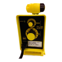
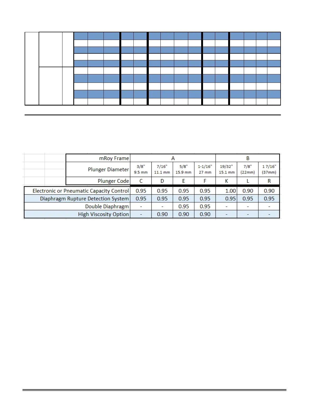
Figure 11. mRoy Pump (All Models) Capacity Derating Table
NOTES:
Certain options require that the maximum capacity be derated. Multiply capacities in the
capacity / pressure tables in Figures 7 through 10 by the appropriate factors in the table above.
mRoy PUMP FLOW DERATING TABLE
B
7/8”
22.2 mm
L
38 48 40 10.0 37.9 4.7 17.8 150 10.3 8.33 31.5 3.9 14.8 150 10.3
25 72 60 16.0 60.6 11.0 41.6 150 10.3 13.33 50.5 9.2 34.7 150 10.3
19 96 80 21.0 79.5 16.0 60.6 150 10.3 17.50 66.2 13.3 50.5 150 10.3
12 144 120 30.4 115.1 25.6 96.9 150 10.3 25.33 95.9 21.3 80.7 150 10.3
10 - 148 150 10.3 31.24 118.2 26.31 99.6 150 10.3
1 - 7/16”
36.5 mm
R
38 48 40 27.0 102.2 21.0 79.5 150 10.3 22.50 85.2 17.5 66.2 150 10.3
25 72 60 42.0 159 36.0 136.3 150 10.3 35.00 132.5 30.0 113.6 150 10.3
19 96 80 57.0 215.7 51.0 193 150 10.3 47.50 179.8 42.5 160.9 150 10.3
12 144 120 85.0 321.7 79.0 299 150 10.3 70.83 268.1 65.8 249.2 150 10.3
10 - 148 - - - - 150 10.3 87.36 330.6 81.19 307.3 150 10.3
Figure 9. mRoy B Plastic Liquid End Capacity Tables
 Loading...