8 Installation, Operations & Maintenance Manual
1.1 INTRODUCTION
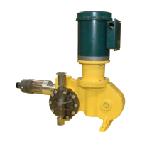
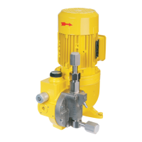
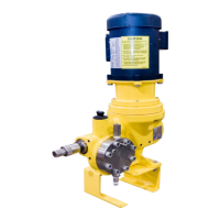
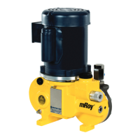
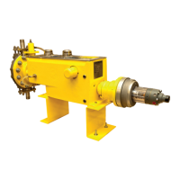
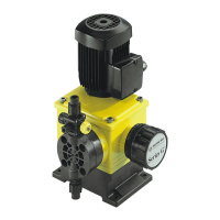
The mRoy pump is a highly reliable controlled
volume pump of hydraulically actuated diaphragm
design. The family of MRA & MRB frame pumps are
further broken down into Model Codes. For ease
of discussion, this manual will refer to either frame
size as MRA and MRB rather than the specic
Model Code.The product codes for the MRA &
MRB are given in Figures 3 and 4. Historical Model
Codes prior to 1995 found in Appendix A.
1.2 GENERAL INFORMATION
Pump capacity is adjustable while the pump is
running or stopped. Capacity adjustment can be
made manually or automatically by a signal from
remote control instruments.
Repetitive accuracy of the metered discharge
volume is maintained within a ±1% range at
constant conditions of pressure, temperature and
pump capacity adjustment setting.
The mRoy pump is a reliable, compact, controlled
volume diaphragm pump for normal corrosive or
toxic chemicals and light slurries with viscosities up
to 200 S.S.U. (40 CPS). For higher viscosities, the
mRoy ”V” option available to 12,200 CPS.
A plunger, reciprocating at a xed stroke, displaces
a xed volume of hydraulic liquid, which actuates a
exible, chemically inert PTFE diaphragm to create
pumping action. Double ball check valves are used
on the suction and discharge to insure consistent
metering accuracy. Capacity control is established
by adjusting the volume of hydraulic liquid, which
bypasses the diaphragm cavity.
Metering with repetitive accuracy is possible only if
the volume of the hydraulic oil in the displacement
chamber is maintained constant for each stroke.
This is accomplished by mechanically opening
the displacement chamber to the oil reservoir for
a short period at the end of every suction stroke
and the beginning of each pressure stroke. During
this period air or vapor is bled from the system,
lost oil is replenished, and allowances are made
for the expansion or contraction of the oil due to
temperature change. For more information, refer
to Principle of Operation.
1.3 PUMP CHARACTERISTICS
For a general description of the mRoy pump you
have purchased, compare the model number and
product code printed on the pump’s data plate
shown in Figure 3 to the appropriate model number
and product code shown in Figures 4 through 6
and Figure 13.
1.4 PUMP PERFORMANCE
The charts in Figures 8 through 10 show the
performance ranges for all mRoy A & B pumps. If
appropriate, refer also to the derating table shown
in Figure 11.
1.5 PRINCIPLE OF OPERATION
Pumping action is developed and controlled by
four basic components as follows (Figures 1 & 2)
1. The pump plunger “A” reciprocates with a
constant stroke length and displaces oil into and
out of the diaphragm chamber “C”.
2. The exible diaphragm “X” is a movable partition
between the plunger oil and liquid being
pumped.
3. An oil bypass circuit from the diaphragm
chamber “C” to the reservoir “D” through
passage “E” bypass port “H” and control spool
valve “F.”
4. A bypass control plunger “G” which moves with
and is directly coupled to the pump plunger to
correlate bypass shut off at port “H” to pump
plunger position.
In operation, as the pump plunger and bypass
control plunger move forward as shown in
Figure 1, the displaced oil is bypassed to the oil
reservoir until the control plunger “G” closes the
SECTION 1 - GENERAL DESCRIPTION

 Loading...
