25Installation, Operations & Maintenance Manual
SECTION 3 - OPERATION
capacity to 100%, or if possible reduce the
discharge pressure to atmospheric pressure for
30 seconds to one minute).
The pump is now ready for calibration. Calculate
what the desired capacity as a percentage of
either the maximum capacity rating on the pump
data plate, or the nominal capacity at the required
system pressure. Each pump is tested at the
factory to conrm that the performance meets
these capacity-pressure requirements (tested
with water). Milton Roy offers a complete line of
calibration columns for calibrating the pump.
Start-Up after the Suction System has Run Dry
In applications where the suction tank does not
have a low level cutoff interconnected into the
pump motor circuit, the pump may occasionally run
dry. This should be avoided to ensure full integrity of
the diaphragm. Running the pump dry occasionally
for no longer than 2 minutes will not harm the
diaphragm or the pump. However, when the pump
is repeatedly allowed to run dry, especially for long
periods of time, the diaphragm is fatigued and could
fail before the next scheduled replacement.
Before restarting a pump that has run dry,
provisions should be made for lling the liquid
end with liquid by opening the discharge line to
atmospheric pressure to either rell liquid end
with ooded suction pressure or start pump with
open discharge and run for a short period of time
(up to 2 minutes) that will ‘prime’ the liquid end if
the ball checks are wet. If these steps fail, remove
the discharge cartridge and ll liquid end with
liquid through the top discharge opening in the
head. After establishing ow, return to the regular
discharge system conguration.
3.2 RESETTING THE RELIEF VALVE
DESCRIPTION
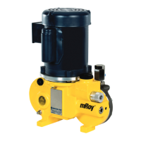
The mRoy pump incorporates an internal relief
valve that is preset at the factory to relieve
when the hydraulic liquid pressure exceeds
125 PSI (8.6 Bar). This setting can be readjusted
as required up to 15% above the maximum rated
pressure of the pump. Resetting the internal relief
valve will change the potential discharge pressure
of the pump.
Refer Figure 18 for a pictorial description of the
mechanism.
Examination of these figures will reveal a
small passage connecting the oil side of the
diaphragm head cavity with the oil reservoir
(See Figures 1 & 2). This passage is stopped off by
a poppet that is held in place by a spring secured
by a set screw. A plastic screw plug keeps the
adjusting threads free of dirt.
In operation, the spring-loaded poppet is held
against the seat in the housing until the pressure
in the oil side of the diaphragm cavity exceeds
the pressure for which the valve has been set.
When this occurs, the poppet is forced off its seat,
permitting the oil to ow from the diaphragm cavity
through the mechanical passage to an opening
(Figure 17) in the side of the oil reservoir. The
resilient material of the poppet permits the relief
valve to actuate without erosion of the poppet or
seat surface.

 Loading...
