A7™ Service Manual 046-006272-00 1 - 51
Theory of Operation Ventilator UI
Display Control Signal Interface, J6
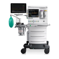
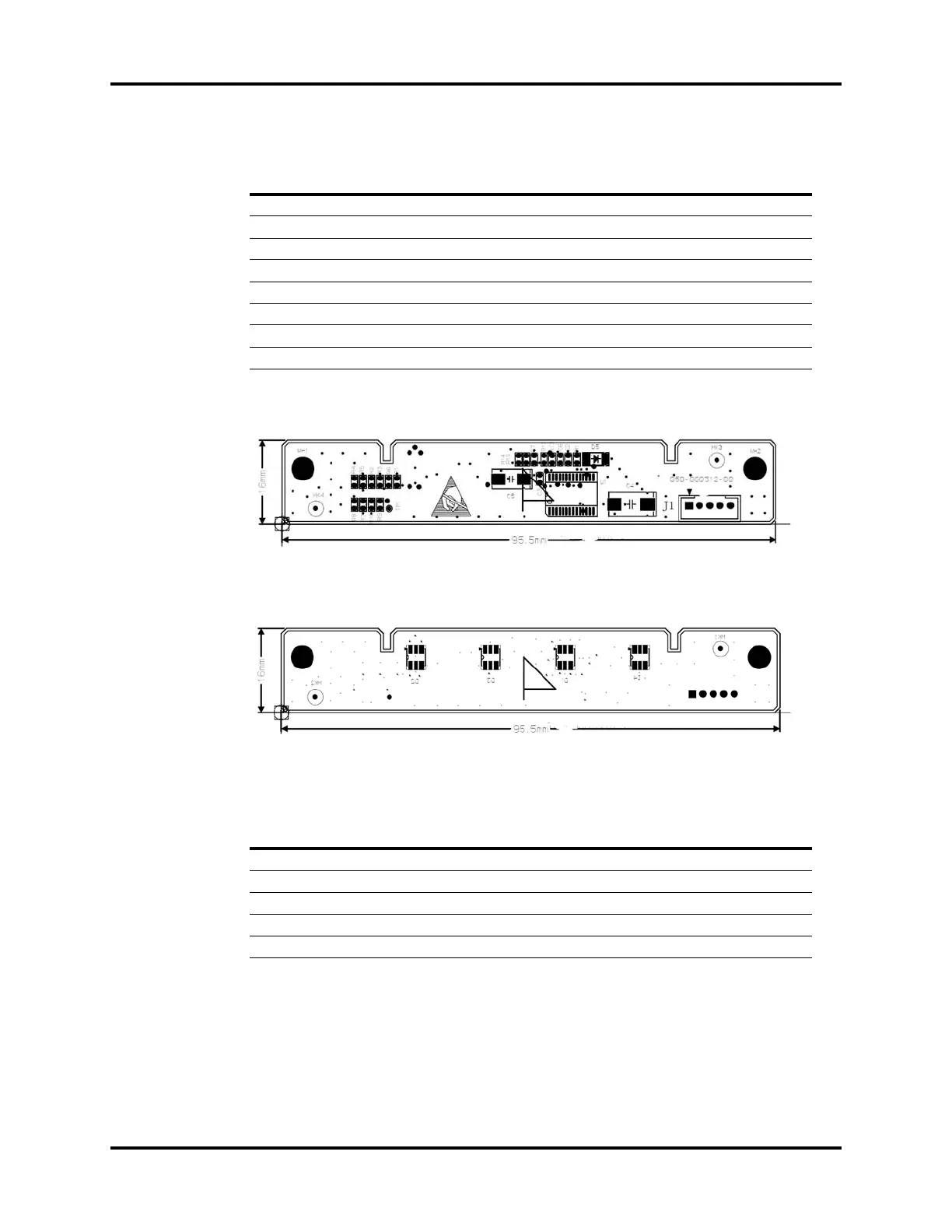
1.6.1.2 Warning Light Board
FIGURE 1-57 Warning Light Board, Top View
FIGURE 1-58 Warning Light Board, Bottom View
Warning Light Board Interface, J1
1.6.1.3 Display and Touchscreen
The anesthesia machine is fitted up with a 15-inch 24-bit 1024x768 LVDS display as the main output
component, and a 15-inch touchscreen as the main input component (another touchpad is available
on the A7 anesthesia machine).
PIN Name Function
1VCC 5 V Power Supply
2GND Ground
3Encoder_A1 Output A of Encoder 1
4Encoder_B1 Output B of Encoder 1
5 Encoder_Y1 Depress of Encoder 1 (Reserved)
6Encoder_A2 Output A of Encoder 2
7Encoder_B2 Output B of Encoder 2
8 Encoder_Y2 Depress of Encoder 2 (Reserved)
PIN NAME FUNCTION
1 12V 12V Power Supply
2GND Ground
3 MAIN_BRD_SDA CPU Board I2C Data Signal
4 MAIN_BRD_SCL CPU Board I2C Clock Signal
53_3V 3.3V Power Supply

 Loading...