BeneVision N17/BeneVision N15/BeneVision N12 Patient Monitor Service Manual 2-3
2.2.2 Internal Module Rack COM Board
Two models of internal module rack COM boards are available. The N12 uses the 4-slot COM board, and
the N15/N17 uses the 6-slot COM board. The internal module rack COM board is used to provide the
interface for communication with the parameter module, the SMR interface and nurse call interface, and
the MPAN module interface. Besides, the data forwarding FPGA and corresponding power circuit are also
provided on the internal module rack COM board.
2.2.3 Power Architecture
AC
/
DC
module
100
~
240
V AC
AC-DC in
Battery
BAT
charger
switch
M0
DC/DC
+12
V
DC/
DC
LDO
+3.3V_1
VBUS:
9.6~11.1V,
+15
V
ON/OFF
ON/
OFF
+5V
Power switch
board
+5V/+3.3V
+3.3V
Alarm lamp
board
Photo
senseor
Led driver
Recorder
+
12V
LCD&TP
+12V
Internal module rock COM
board
iView module
+12V
Independent display
board
+
5V
+
5V
ON/OFF
+3
.3V
DC/
DC
DC
/
DC
+
3.
3V
_
2
MPAN module
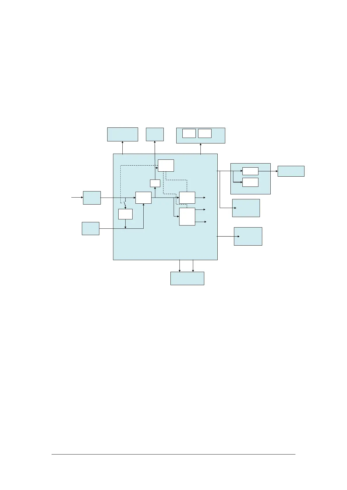
Figure 2-3 Diagram of power architecture
The AC/DC power module outputs 15V to the main control board, and 3.3V, 5V and 12V can be generated
through the internal DC-DC conversion circuit in the main control board to provide a power supply to
other modules or boards in the main unit. The battery charging circuit is powered by 15V, and the AC
power supply and battery power supply can be switched according to AC on-line detection.
The +12V power supply is provided to the power supply, including the external module rack, and the
DC-DC isolation design is implemented at the module end.
The iVIew assembly uses the power rail Vbus, which is the switching output between the AC-DC output
and battery and aims to avoid abnormal power failure of the iView module and running exception of the
Windows OS running on other modules due to an unexpected power failure of the AC power supply. The
battery supports the main unit to stop the iView module in the normal power-off mode. In the case of
battery power supply, the iView module cannot start.
 Loading...