L1
L2
S1
S2
S3
TB1
L2
L3
ECB1
L
N
ECB2
N
L3
L1
S1
S2
S3
L
N
35
Power
supply
3N~
400 V
50Hz
Earth
leakage
circuit
breaker
*
1,
*
2
Wiring
circuit
breaker
or
Isolating
switch
Powersupply
3~ 400 V50Hz(EH*T20*-YM*C)
3~ 230 V50Hz(EH*T20*-TM*C)
Power
supply
~/N
230 V
50Hz
Wiring
circuit
breaker
or
Isolating
switch
Wiring
circuit
breaker
or
Isolating
switch
For
booster
heater
(Primary circuit)
For
Immersion
heater
(DHW tank)
To control
board
Outdoor unit
Cylinder unit
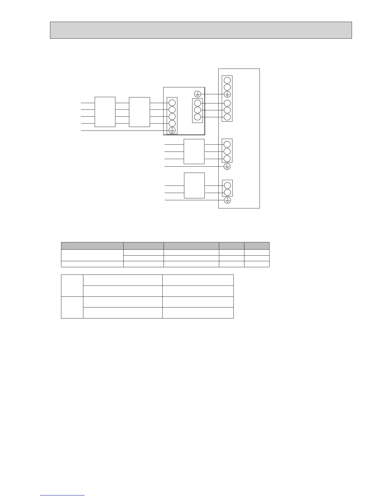
<3 phase>
<Figure7-2>
Electrical connections 3 phase
Description Power supply Capacity (Indoor unit Ref.) Breaker Wiring
Booster heater (Primary circuit)
3~400V50Hz 9 kW 16 A
*
2
2.5 mm²
3~230V50Hz 9 kW 32 A
*
2
6.0 mm²
Immersion heater (DHW tank) ~/N230V50Hz 3 kW 16 A
*
2
2.5 mm²
Wiring
WiringNo.
×size(mm²)
Cylinder unit - Outdoor unit
*
3
3 × 1.5 (polar)
Cylinder unit - Outdoor unit earth
*
3
1 × Min. 1.5
Circuit
rating
Cylinder unit - Outdoor unit S1 - S2
*
4
230 V AC
Cylinder unit - Outdoor unit S2 - S3
*
4
24 V DC
*
2
Abreakerwithatleast3.0mmcontactseparationineachpoleshallbeprovided.Useearthleakagebreaker(NV).
The breaker shall be provided to ensure disconnection of all active phase conductors of the supply.
*
3
Maximum45m
If2.5mm²isused,maximum50m.
If2.5mm²isusedandS3isseparated,maximum80m.
*
4
Thevaluesgiveninthetableabovearenotalwaysmeasuredagainstthegroundvalue.
Notes: 1. Wiring size must comply with the applicable local and national codes.
2.Indoorunit/outdoorunitconnectingcordsshallnotbelighterthanpolychloroprenesheathedexiblecord.(Design60245IEC57)
Indoorunitpowersupplycordsshallnotbelighterthanpolychloroprenesheathedexiblecord.(Design60227IEC53)
3. Install an earth line longer than power cables.
4.Pleasekeepenoughoutputcapacityofpowersupplyforeachheater.Insufcientpowersupplycapacitymightcausechattering.
*
1
Iftheinstalledearthleakagecircuitbreaker
does not have an over-current protection
function,installabreakerwiththatfunction
alongthesamepowerline.
AfxlabelAthatisincludedwiththemanualsneareach
wiringdiagramforcylinderunitandoutdoorunits.

 Loading...
