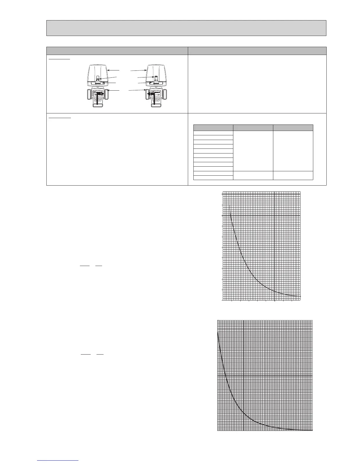
Part Name Check Points
3-way valve
AB
AB
A
A
B
A
B
Motor
Valve
Indicator (red)
Release button
B
<DHW> <Heating>
AB
(1) Check the movement of the red indicator. The red indicator normally points
toAinDHWmodeandtoBinHeatingmodeasshowntotheleft.
(2)Ifeachindicatorpositioniscorrectbutthe3-wayvalvedoesnotworkprop-
erly,themotormaynottontothevalvesecurely,soremovethemotorby
pressingthereleasebutton,andreinstallit.
Thermistors Disconnecttheconnectorthenmeasuretheresistancewithatester.
(Atambienttemperaturesof10–30°C.)
Thermistor Normal Abnormal
TH1
4.3–9.5kΩ Open or short
TH2
THW1
THW2
THW5
THW6
THW7
THW8
THW9
THWB1
40–100kΩ Open or short
THWB2
•Boilerflowwatertemperaturethermistor(THWB1)
•Boilerreturnwatertemperaturethermistor(THWB2)
0
10
20
30
40
50
-20 -10 0 10 20 30 40 50
Temperature (:)
Resistance (k")
<Thermistor Characteristics Charts>
•Roomtemperaturethermistor(TH1)
•Liquidrefrigeranttemperaturethermistor(TH2)
•Flowwatertemperaturethermistor(THW1)
•Returnwatertemperaturethermistor(THW2)
•DHWtanktemperaturethermistor(THW5)
•Zone1owwatertemperaturethermistor(THW6)
•Zone1returnwatertemperaturethermistor(THW7)
•Zone2owwatertemperaturethermistor(THW8)
•Zone2returnwatertemperaturethermistor(THW9)
0°C 15kΩ
10°C 9.6kΩ
20°C 6.3kΩ
25°C 5.2kΩ
30°C 4.3kΩ
40°C 3.0kΩ
ThermistorR0=15kΩ ± 3%
Bconstant=3480±2%
Rt=15exp{3480(
273+t
–
273
)}
1
1
0
100
200
300
400
500
600
700
800
900
1000
-30 -20 -10 0 10 20 30 40 50 60 70 80
Temperature (°C)
Resistance (kΩ)
0°C 162.8kΩ
10°C 97.4kΩ
20°C 60.3kΩ
25°C 48.1kΩ
30°C 38.6kΩ
40°C 25.4kΩ
50°C 17.1kΩ
60°C 11.9kΩ
70°C 8.4kΩ
80°C 6.0kΩ
ThermistorR100=3.3kΩ±2%
Bconstant=3970±1%
Rt=3.3exp{3970(
273+t
–
273
)}
1
1
77

 Loading...
