DISASSEMBLY PROCEDURE
PHOTOS
85
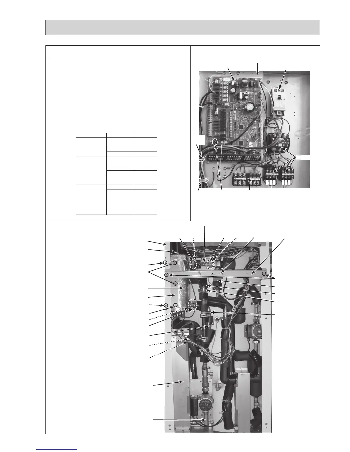
8. How to remove the booster heater
(1) Remove the front panel (Refer to Procedure 1).
(2) Disconnect the CNBHT connector on the controller
board,andtheboosterheaterleadwireswiredtothe
BHC1(LeadwireNo.1,No.2andNo.3)andBHC2
(LeadwireNo.4,No.5andNo.6)contactorsrespectively
andreleasetheleadwiresfromthefastener,thecable
clamp, the 2 cable straps, the coated clamp and the 3
bands. (Photos 8-1 and 10-1)
Note:Donotmixuptheleadwirenumberswhen
re-connectingtheleadwirestothecontactorsas
theleadwirenumbersaredifferentdependingon
the models.
Model LeadwireNo. Contactor
EHST20C-VM6C
EHST20C-VM6EC
EHPT20X-VM6C
No.1 BHC1-U
No.2 BHC1-V
No.3 BHC2-U
No.4 BHC2-V
EHST20C-YM9C
EHST20C-TM9C
EHST20C-YM9EC
EHPT20X-YM9C
EHPT20X-TM9C
EHST20D-YM9C
No.1 BHC1-U
No.2 BHC1-V
No.3 BHC1-W
No.4 BHC2-U
No.5 BHC2-V
No.6 BHC2-W
EHST20C-VM2C
EHST20C-VM2EC
EHST20D-VM2C
EHST20D-VM2EC
EHPT20X-VM2C
ERST20C-VM2C
ERST20D-VM2C
No.1 BHC1-U
No.2 BHC1-V
Refer to 6. WIRING DIAGRAM
ThephotosshownareoftheEHST20C-VM6Cmodel.
Screw
Flare nut
Photo 8-1
Photo 8-2
Pipe (W.C. - B.H.)
Terminal
block (TB1)
Earthleakagecircuit
breaker (ECB1)
Contactors
ControlboxController
board
CNBHT
connector
Gasket
(G1")
Heater stay
P-HEX
Booster heater
Screw
Quickconnectionof
inlet of booster heater
Quickconnection
of outlet of P-HEX
Band and rubber
Pump valve
Nut
(G1")
Gasket
(G1")
Nut
(G1")
Continuetothenextpage.
No.1
No.2
No.3
No.4
No.5
No.6
Cable
clamp
Cable
strap
Front frame (L)
Screws
Screw
O-ring
O-ring
Pipe (B.H.-D.V.)
Band
DIV frame
Screws
Cushion
Pipe (to F.S.)
Quickconnection
(upper F.S.)

 Loading...
