PHOTOS
80
DISASSEMBLY PROCEDURE
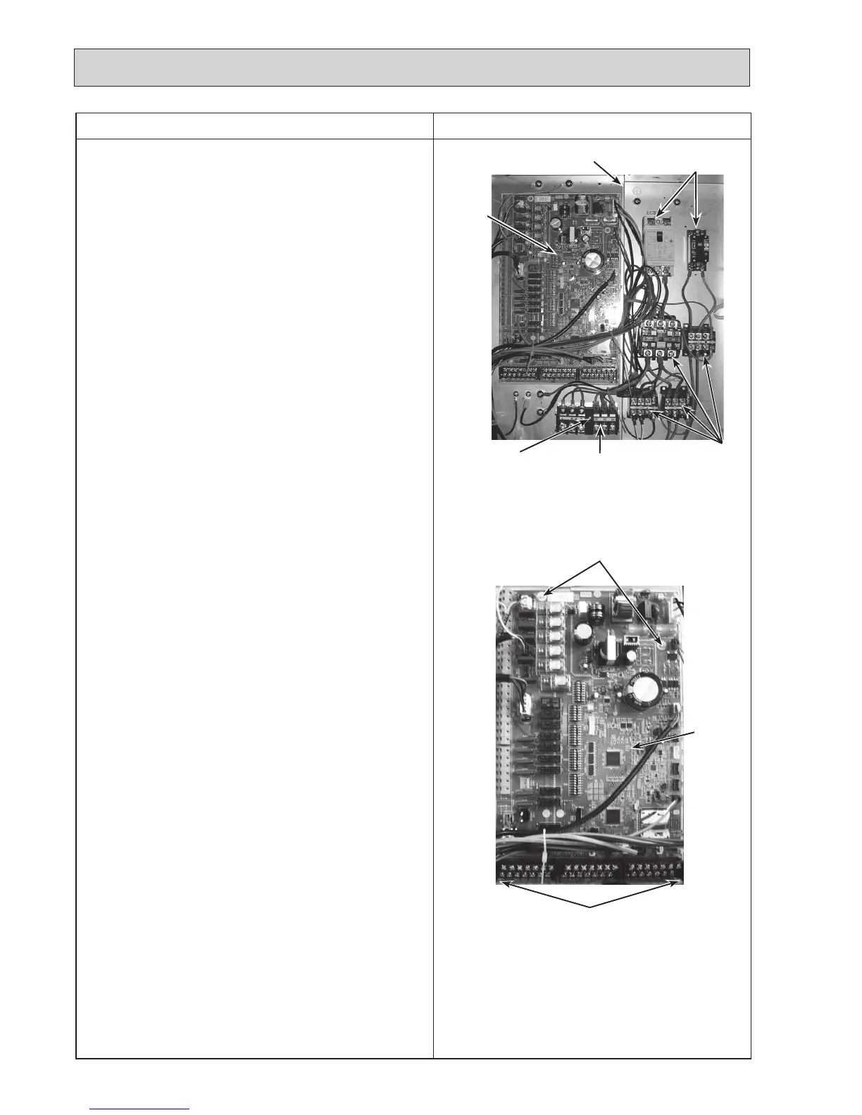
Photo 3-2
Photo 3-1
3. How to remove the electrical parts
(Step(1)isappliedtoallthefollowingparts.)
(1) Remove the front panel (Refer to Procedure 1).
<Earth leakage circuit breaker> (Photo 3-1)
(2)Disconnectalltheleadwiresfromtheearthleakagecir-
cuit breaker.
(3)
Removethe2screwsontheearthleakagecircuitbreaker.
Note:
To avoid dropping of the breaker, hold the breaker by
hand when removing the last screws.
<Contactor> (Photo 3-1)
(2)Disconnectalltheleadwiresfromthecontactors.
(3)Removethe2screwsoneachcontactor.
Note:
To avoid dropping of the contactors, hold the contac-
tors by hand when removing the last screws.
To prevent an electrical shock, wait until all the LED
lamps on the FTC control board are turned off.
<Terminal block> (Photo 3-1)
(2)Disconnectalltheleadwiresfromtheterminalblock.(To
disconnecttheS1,S2andS3leadwires,disengagethe
locksbypressingontheclaws.)
(3)Removethescrewontheterminalblock.
Note:
To avoid dropping of the terminal block, hold the
terminal block by hand when removing the screw.
<Controller board> (Photo 3-2)
(2)Disconnectalltheleadwiresfromthecontrollerboard.
(3) Remove the controller board from the 4 board supports.
ThephotosshownareoftheEHST20C-VM6Cmodelwith
optional immersion heater.
Terminal block (TB1)
Earthleakagecircuit
breakers (ECB1, ECB2)
Contactors
Controlbox
Controller
board
Controller
board
Screw
Board supports
Board supports

 Loading...
