DISASSEMBLY PROCEDURE
PHOTOS
91
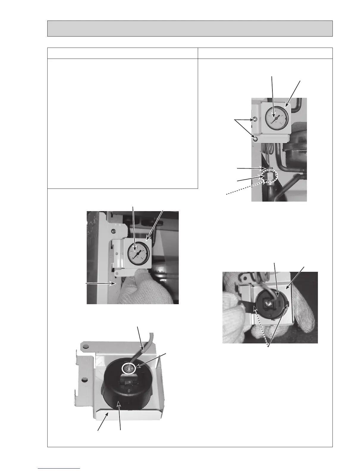
Photo 11-1
11. How to remove the
pressure relief valve/manometer/air
vent (automatic)
(1) Remove the front panel (Refer to Procedure 1).
(2)
Swingthecontrolboxtothefront(RefertoProcedure4).
<Manometer>
(3)RemovetheG1/4"nutfromthepressurereliefvalve
using2spanners:onetoholdthejoint(G1/4")andthe
other to turn the manometer connection. (Photo 11-1)
•WhenreinstallingtheG1/4"nut,useanewG1/4"
gasket.(Photo11-1)
(4)
Removethe2screwsandremovethemanometercover
withthemanometerfromthefrontframe(L)byslidingit
upward.(Photos11-1and11-2)
(5)Removethemanometerfromthemanometercoverwhile
pressingonthe2claws.(Photo11-3)
•Whenreinstallingthemanometerassemblyontheunit,
bewarenottoputstrainontherootofthecapillarytube
as the capillary tube is easy to break at the root. (Photo
11-4)
Photo 11-2
Photo 11-3
Manometer
Manometer
cover
Screws
Photo 11-4
Manometer
connection (G1/4")
Joint (G1/4")
Gasket
(G1/4")
Manometer
Manometer
cover
Front frame (L)
Manometer
Manometer
cover
Claws
Manometer
Manometer
cover
Root
Capillary tube
Continuetothenextpage.

 Loading...
