PHOTOS
DISASSEMBLY PROCEDURE
84
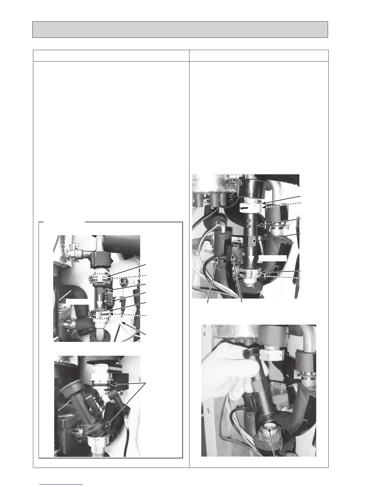
7. How to remove the flow sensor
(1) Remove the front panel (Refer to Procedure 1).
(2) Disconnect the CN1A connector on the controller board.
(Photo 4-2)
(3)Releasetheflowsensorleadwirefromthecableclamp,
thefastenerandthecablestrapinthecontrolbox,and
thecablestrap,thecoatedclampandthe3bandsbelow
thecontrolbox.(Photos4-1and10-1)
(4) Close (OFF) the strainer valve. (Photo 5-1)
•
Whenthestrainervalvehandleisstiff,useatooltogrip
the handle and turn it carefully.
•
Whenopeningorclosingthestrainervalve,ensuretodo
sofully,nothalfway.
(5)Loosenthenutsusing2spanners,andremovetheflow
sensor;onetoholdtheflowsensorandtheothertoturn
the nut. (Photos 7-1 and 7-2)
•Whenreinstallingtheflowsensor,usenewO-rings.
(Photos 7-1 and 7-2)
Photo 7-1
Photo 7-2
Sensor part
O-ring
Leadwire
Nut(G1")
O-ring
Place to hold
theflowsen-
sorwitha
spanner
Flowdirection
Nut(G1")
O-ring
Flowsensor
Photo 7-3
Photo 7-4
Sensor part
Leadwire
O-ring
Flowdirection
O-rings
Flowsensor
R2 models
Same diameter
quick connection
O-ring
<For R2 models>
(5)Removetheflowsensorbydetachingthesame
diameter quick connection. (Photos 7-3 and 7-4)
•Whenreinstallingtheflowsensor,usenewO-rings.
(Photos 7-3 and 7-4)
•RefertoProcedure23forhowtoattachand
detach the quick connection.
Note:Settheflowsensorinthedirectionofthearrow
printedontheflowsensor,andinthewaythatthe
sensorpartfacestotheleft(rightforR2models).
(Photo 7-1 and 7-3)
Same diameter
quick connection

 Loading...
