32
33
18
17
30
30
35
37
21
3
4
25
28
7
5
15
13
29
23
32
14
6
7
24
36
12
26
38
WATER SYSTEM DIAGRAM
8
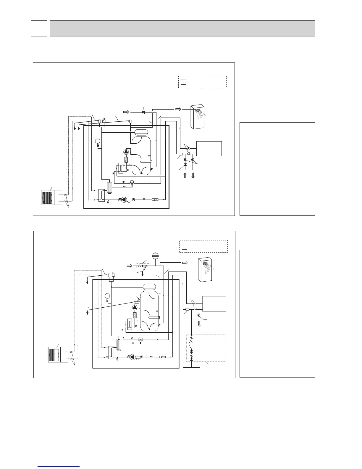
•Refer to <Table 4-1 and 4-2> for the part names.
*1Refertothefollowingsection[Localsystem].
<E*ST20*-*M**C > (Split model system)
<EHST20*-MHCW>(UKSplitmodelsystem)<Example>
<Figure8-2>
<Figure8-1>
Notes:
•Toenabledrainingofthecylinderunit
an isolating valve should be posi-
tioned on both the inlet and outlet
pipework.
•Besuretoinstallastrainerontheinlet
pipeworktothecylinderunit.
•Suitabledrainpipeworkshouldbeat-
tached to all relief valves in accord-
ancewithyourcountry’sregulations.
•Abackowpreventiondevicemustbe
installed on the cold water supply
pipework(IEC61770)
• When using components made from
different metals or connecting pipes
made of different metals insulate the
joints to prevent any corrosive reac-
tion taking place which may damage
thepipework.
Flare connection
Flare connection
Cylinder unit
Cylinder unit
Drain
Drain
Drain
Drain
Drain
Drain
Coldwater
Coldwater
DHW
DHW
Local system
Refrigerantpipe
Water pipe
Local system
Flexiblehose
(Temporary connection)
Water
supply
Notes:
•
To enable drainingofthecylinderunit
anisolatingvalveshouldbepositioned
onboth the inlet and outlet pipework.
Novalveshouldbettedbetweenthe
expansionvalve(item35)andthecyl-
inder unit (safety matter).
•Besuretoinstallastrainerontheinlet
pipeworktothecylinderunit.
•Suitabledrainpipeworkshouldbeat-
tached to all relief valves in accord-
ancewithyourcountry’sregulations.
• When using components made from
different metals or connecting pipes
made of different metals insulate the
joints to prevent any corrosive reac-
tion taking place which may damage
anypipework.
•Fillingloop’sexiblehosemustbere-
movedfollowingthellingprocedure.
Item provided with unit as loose ac-
cessory.
•Installtheinletcontrolgroup(item35)
abovetheleveloftheT&Preliefvalve
(item21).Thiswillensure DHW tank
willnotrequiredrain-downtoservice/
maintaintheinletcontrolgroup.
Refrigerantpipe
Water pipe

 Loading...
