PHOTOS
82
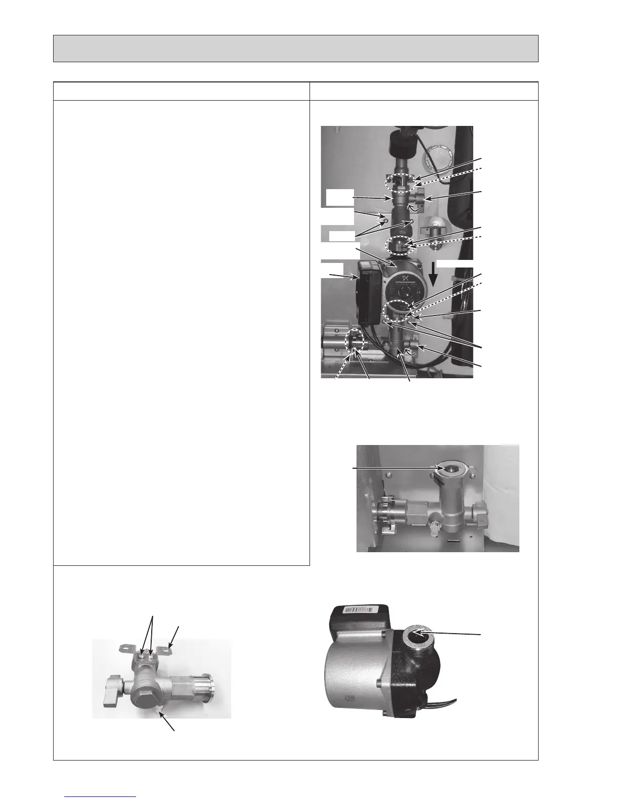
5. How to remove water pump (primary circuit)/pump valve/
strainer valve
<Water pump>
(1) Remove the front panel (Refer to Procedure 1).
(2) Disconnect the CNP1 connector, the earth cable and the
CNPWMconnectorinthecontrolbox.(Photo4-2)
(3)Releasethewaterpumpleadwirefromthe2cable
clamps, the fastener and the cable strap in the control
box,andthecablestrap,thecoatedclampandthe3
bandsbelowthecontrolbox.(Photos4-1and10-1)
(4) Close (OFF) the pump valve and the strainer valve
(Photo 5-1)
•
When either of the pump valve handle or the strainer
valvehandleisstiff,useatooltogripthehandleand
turn it carefully.
• Whenopeningorclosingthepumpvalveandthe
strainervalve,ensuretodosofully,nothalfway.
(5)RemovethewaterpumpbyremovingthetwoG1"nuts
usingthe2spanners:onetoholdtheG1"nutandthe
othertoturntheothersideofG1"nut.Removethewater
pumpbyslidingithorizontally.(Photo5-1).
•WhenreinstallingtheG1"nuts,usenewG1"gaskets.
(Photos 5-2 and 5-3)
• Setthewaterpumpinthewaythatthediestamped
arrowfacingdown,andtheterminalboxfacingtothe
left.
<Pump valve>
(6)Removethe2screwsonthepumpvalvestay.(Photo
5-1)
(7)
Removethepumpvalvebydetachingthequickconnection.
• Whenreinstallingthequickconnection,usenewO-ring.
•
RefertoProcedure23forhowtoattachanddetachthe
quick connection.
(8)
Removethepumpvalvestaybyremovingthe2screws,
and remove the drain cock (primary circuit). (Photo 5-4)
• Reuse the removed pump valve stay and the pump
valvestayfixingscrews.
• Whenreinstallingthedraincock(primarycircuit),usea
newone.
Note:SkipSteps(2)and(3)abovewhenreplacingthe
pump valve only.
Photo 5-1
Photo 5-2
Photo 5-3
DISASSEMBLY PROCEDURE
Quickconnection
O-ring
Strainer
valve
Water pump
(primary circuit)
Nut(G1")
Gasket(G1")
Terminal
box
Quick
connection
Strainer valve
handle
Pump valve
Pump valve
handle
Nut(G1")
Gasket(G1")
Gasket
(G1")
Gasket(G1")
O-ring
Strainer
valve stay
Screws
Screws
Pump valve stay
Continuetothenextpage.
Photo 5-4
Screws
Flowdirection
Pump valve stay
Drain cock
(primary circuit)

 Loading...
