PHOTOS
81
Bracket (R)
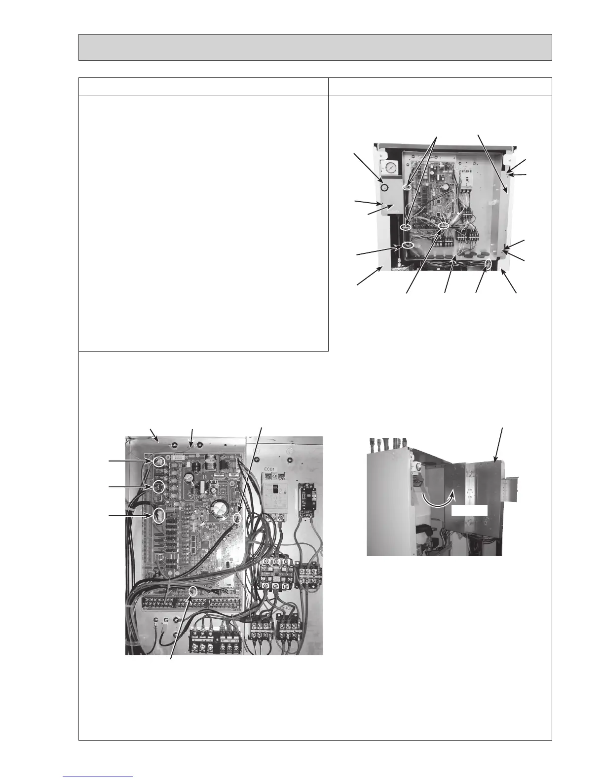
DISASSEMBLY PROCEDURE
Photo 4-1
Photo 4-3
4. How to remove the control box
(1) Remove the front panel (Refer to Procedure 1).
(2)Disconnectonlytheleadwiresinthecontrolboxthat
connect to the components in the cylinder unit.
Photo4-2showsthecontrolboxbeforetherelatedlead
wiresaredisconnected.
(3)Removethe3screwsonthebracket(LandR)and
disengagethetabonthecontrolboxbracketfromthe
front frame (L). (Photo 4-1)
(4)Disengagethe2tabsonthecontrolboxbracket(R)from
the front frame (R). (Photo 4-1)
(5)Slightlyliftandpulloutthecontrolboxfromthecylinder
unitwhiletiltingthecontrolboxbackward.
<When swinging the control box to the front>
(2
)
Removethe3screwsonthebracket(LandR).(Photo4-1)
(3)Disengagethetabonthecontrolboxbracket(L)from
thefrontframe(L)andpullthecontrolboxbyliftingthe
left-handsidetoswingthecontrolbox.(Photo4-3)
Note: Disconnect the field wiring as necessary.
ThephotosshownareoftheEHST20C-YM9Cmodel.
Controlbox
Front
frame (R)
Swing
Bracket (L)
Cable
clamps
Cable
strap
Photo 4-2
Screw
Front
frame (L)
ThephotosshownareoftheEHST20C-VM6Cmodelwith
optional immersion heater.
Screw
Control
box
Tab
Tab
Tab
Fastener
CN1A connector
CNV1
connector
CNPWM connector
CNP4
connector
CNP1
connector
Earth cable of
waterpump
(primary circuit)
Earth cable of
waterpump
(sanitary circuit)
Cable
strap
Screw

 Loading...
