Part Name Check Points
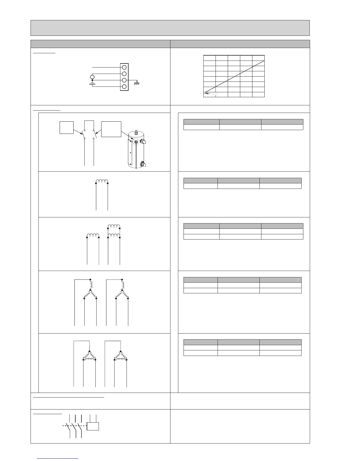
Flow sensor
Booster heater Measuretheresistancebetweentheterminalswithatester.
Thermostat(90°C)andthermalcutout(121°C)
90 °C
Manual reset
water
thermostat
121 °C
Thermal
cut-out
AWG18
AWG18
9
10
Terminal Normal Abnormal
9–10 110(±35)mΩ Open or Short
2 kW heater (230 V, 1 phase)
1
2
2kW
AWG15 FEP
WHITE
AWG15 FEP
WHITE
Terminal Normal Abnormal
1–2 26.5(+3/−1.3)Ω Open or Short
2 + 4 kW heater (230 V, 1 phase)
1
2
2kW
AWG15 FEP
WHITE
AWG15 FEP
WHITE
3
4
2kW
AWG13 FEP
BLUE
AWG13 FEP
BLUE
2kW
Terminal Normal Abnormal
1–2 26.5(+3/−1.3)Ω Open or Short
3–4 13.3(+1.5/−0.6)Ω Open or Short
3 + 6 kW heater (400 V, 3 phase)
5 6
AWG13 FEP
BLUE
AWG13 FEP
BLUE
AWG15 FEP
WHITE
2kW
4
AWG13 FEP
BLUE
2kW 2kW
2 3
1kW
1
1kW 1kW
AWG15 FEP
WHITE
AWG15 FEP
WHITE
Terminal Normal Abnormal
1−2=2-3=1−3 105.8(+11.8/−5)Ω Open or Short
4−5=5-6=4−6 52.9(+5.8/−2.5)Ω Open or Short
3 + 6 kW heater (230 V, 3 phase)
Terminal Normal Abnormal
1−2=2-3=3−1
35.3(+3.9/−1.8)Ω Open or Short
4−5=5-6=6−4 17.6(+1.9/−0.9)Ω Open or Short
Earth leakage circuit breaker for heater Ifashortcircuitoccursontheboosterheater,immersionheater,oreachpower
line,ashort-circuitbreakerwilltripandpowersourcewillbeblocked.
Eliminatethecausesofshortcircuitandthenturnonthebreakeragain.
Relay for heater
R S T A1 A2
U V W
Whentheappliedvoltageisnot230VACacrosstheterminalsA1-A2,check
the terminals R-U, S-V, and T-W are open.
Whentheappliedvoltageis230VACacrosstheterminalsA1-A2,checkthe
terminals R-U, S-V, and T-W are short.
5 6
AWG13 FEP
BLUE
AWG13 FEP
BLUE
AWG15 FEP
WHITE
4
AWG13 FEP
BLUE
2kW 2kW
2 31
1kW 1kW
AWG15 FEP
WHITE
AWG15 FEP
WHITE
2kW
1kW
Flow signal V
5V DC
CN1A
1
4
Flow signal
4.0
3.5
3.0
2.5
2.0
1.5
1.0
0.5
0.0
0 20 40 60 80 100
Flow [l/min]
Flow output signal[V]
0.35V
76

 Loading...
