6878215A01
5-16 Motorcycle Radio Installation Installing Antenna Base and Cables
6. These holes in the metal liner is used as a template to mark the position of the hole(s) to be
drilled at the top cover. Follow the below guidelines for the various options.
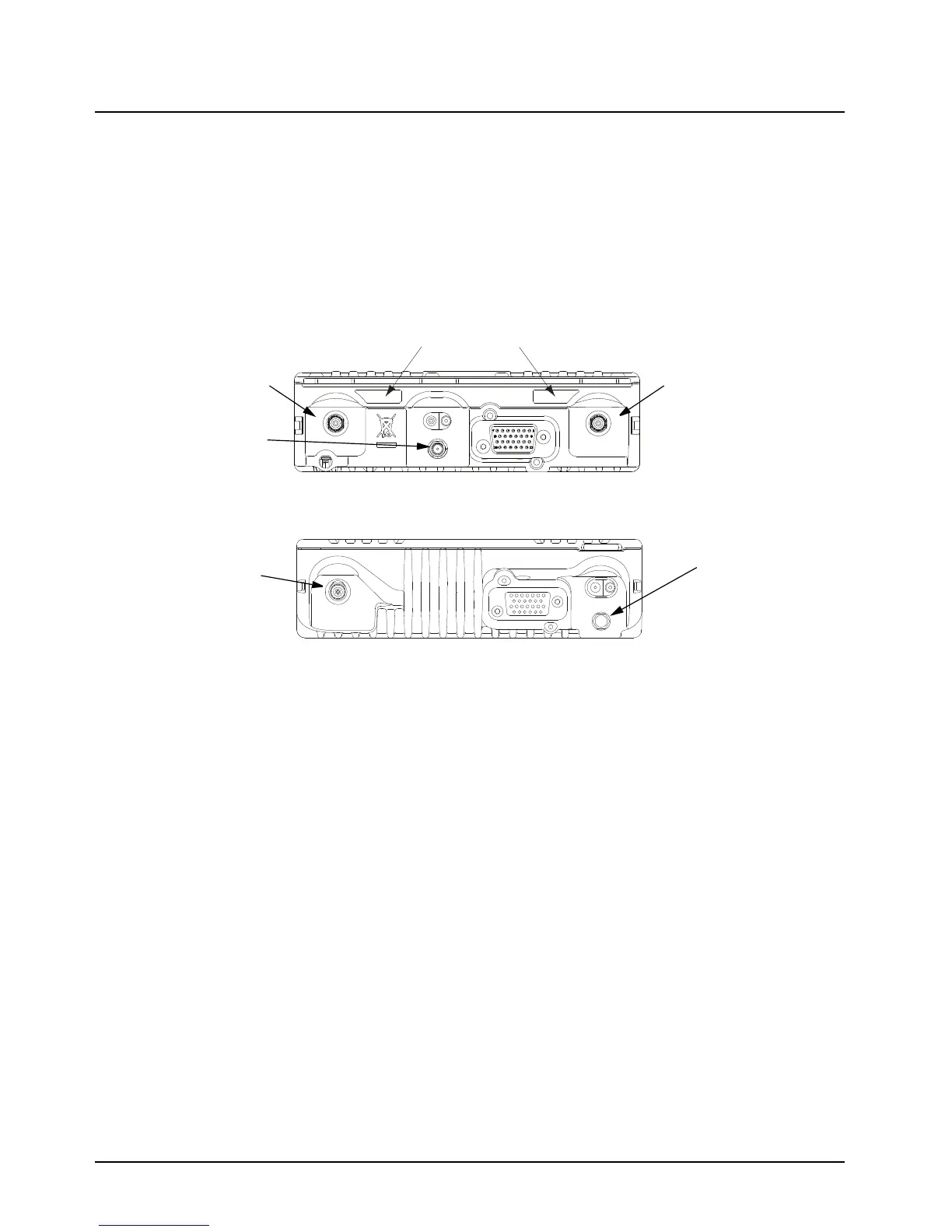
- Single Band – Refer to your APX radio (see Figure 5-9 or Figure 5-10) and see if your
single band antenna is in the position of Band 1 or 2. Depending on which location your
antenna port is mark a hole in the appropriate antenna position only. Refer to Figure 5-8.
- Dual Band – Mark a hole in both the Band 1 and Band 2 Antenna position as seen on
Figure 5-8.
- GPS – Mark a hole in the GPS Antenna position as seen on Figure 5-8.
Figure 5-9. Antenna Band Identification
Figure 5-10. APX 2500/APX 4500 Antenna Band Identification
7. Remove the metal liner from the top cover.
8. For Band 1 and Band 2 positions, use the Motorola RPX-4378A Hole-Cutting Saw or
equivalent, and carefully drill a 3/4-inch hole at the marked location from the inside of the
cover until the saw bottoms out. For the GPS carefully drill a 9/16-inch hole at the marked
location from the inside of the cover until the saw bottoms out. The saw should clean a neat
circle to assure good contact between the antenna and the housing.
IMPORTANT: For proper seating of the antennas, deburr and scrape any foreign
matter from both sides of the hole, being careful not to mar the
finish of the shell.
9. Clean the mounting surface around the hole to remove dirt and wax.
10. Refer to the Motorcycle GPS Instruction Manual for further installation instruction for the
GPS. GPS must be mounted before the APX metal liner is installed.
11. Reinstall the APX metal liner (see Figure 5-8) with the cable clamps provided in the weather-
resistant housing. If installing GPS, the GPS coaxial cable must be fed through the hole in the
APX metal liner before the liner can be placed onto the housing. Then route the GPS Coaxial
Cable through the cable clamps before tightening the hex screws as installing the cable after
that is difficult due to the connector. See Figure 5-11 for GPS Cable Routing.
Band 1 Antenna PortBand 2 Antenna Port
GPS Antenna Port
Antenna Port
GPS Antenna Port
 Loading...


