6878215A01
Standard Configurations Planning the Installation 2-5
NOTE: In dash mount configuration, it is mandatory that a rear accessory cable be attached at the
back of a mid power transceiver, in order to ground the Emergency pin to GND. Or, an
emergency footswitch or pushbutton switch must be attached at the back of a mid power.
If the emergency pin is not grounded, upon the attachment of the A+ cable at the DC
connector, the radio will detect a HIGH for the emergency pin state, and assume that
emergency has been activated. This will attempt to power on the radio, and will result in
excessive current draw and incorrect radio operation. Refer to Section 2.1.3.1 for further
details and recommended wiring of emergency in dash mount.
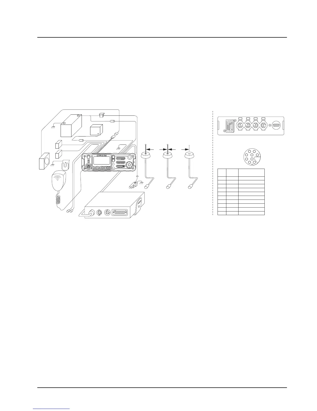
Figure 2-8. Radio Installation (O2 Mid Power Remote Mount)
BATTERY
HORN
RELAY
LIGHT
RELAY
MIC
CLIP
SPEAKER
MIC
EMERGENCY
SWITCH
RED LEAD
FUSE
BLOCK
YELLOW
LEAD
BLACK
LEAD
(+)
(-)
FUSE
FUSE
CONTROL HEAD
FIREWALL
HOLE
ANTENNA
CONNECTION
ANTENNA 1
DC POWER
CABLE
RADIO
FUSE
ANTENNA
CONNECTION
ANTENNA 2
(FOR DUAL
BAND RADIOS)
ANTENNA
CONNECTION
ANTENNA 3
GPS (OPTIONAL)
PWR
SPK
J400-1 RED SWB +
J400-2 GREEN GND
J400-3 - NO PIN
J400-4 - "VIP" detect: GPIO=HIGH
J400-5 BLUE VIP_OUT_1
J400-6 YELLOW VIP_OUT_2
J400-7 BLACK VIP_OUT_3
J400-8 WHITE VIP_IN_1 (VIP_IN GPIO)
J400-9 ORANGE VIP_IN_2 (VIP_IN GPIO)
J400-10 VIOLET VIP_IN_3
CAN CAN DEK
VIP
J400
ACC USB
PORTS ON REAR OF REMOTE CONTROL HEAD
VIP CONNECTOR PIN-OUT
J400
6
9
10
7
4
2
5
8
1
Radio
Pin
Number
VIP Cable
(HKN6196_)
Wire Color
Function
3 ft 3 ft
 Loading...


