6878215A01
Standard Configurations Power Cables (Transceiver and Control Head) 2-33
2.3 Power Cables (Transceiver and Control Head)
Route the RED power cable from both the radio and the control head to the vehicle’s battery
compartment, using accepted industry methods and standards. Be sure to grommet the firewall hole
to protect the cable. Remove the 15-amp (part number 6580283E06), 20-amp (part number
6580283E07) or 30-amp (part number 6580283E09) fuse from the fuseholder and connect the red
lead of the radio power cable to the positive battery terminal using the hardware provided as shown
in Figure 2-46 and Figure 2-47. Connect the black lead to a convenient solid chassis ground point.
DO NOT connect the black lead directly to the battery’s negative terminal.
NOTE: Remote Control Head power cable uses a 5A Fuse (part number 6580283E03).
2.3.1 Optional Locking Feature for High Power Chassis Power Cables
An optional clip (HLN7017_) can be used to increase DC cable retention in the high power radios.
Directions for assembly and disassembly are:
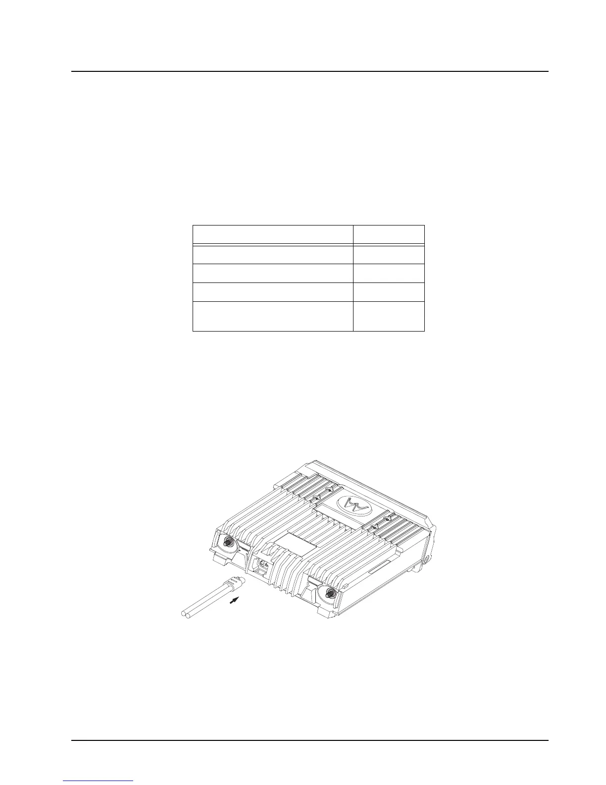
1. Install the DC cable to the radio by aligning the male and female portions of the battery side
with the mating components on the radio side.
Figure 2-41. Bracket Installation
Table 2-9. Power Cables
Description Part Number
Mid Power Dash Mount HKN4191_
Mid Power Remote Mount HKN4192_
High Power Remote Mount HKN6110_
O5, O7, and O9 Remote Control
Head Power Cable
HKN6188_
 Loading...


