6878215A01
4-4 Options and Accessories Installation Remote-Mount Accessory Installation
4.2.2 Horn (External Alarm) Relay Installation
Mount the horn relay in a suitable location (normally under the dash). Connect the relay contacts
across the horn ring switch, typically found in the steering column. Connect the two control wires to a
SW B+ pin and a VIP OUT pin on the VIP connector.
4.2.3 Lights (External Alarm) Relay Installation
Mount the light relay in a suitable location (normally under the dash). Connect the relay contacts
across the head lamp ON/OFF switch. Connect the two control wires to a SW B+ pin and a VIP OUT
pin on the VIP connector.
4.2.4 Gunlock Installation
The O7 or O9 control head can program up to three gunlocks through the programmable buttons.
You can set the time for the momentary trigger using the time-out trigger button. Connect the relay
contacts across the gunlock switch to install the gunlock. Connect the two control wires to a SW B+
pin and a VIP OUT pin on the VIP connector.
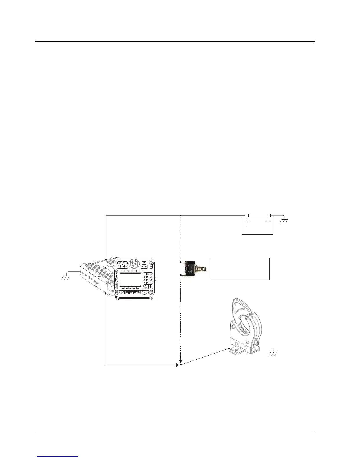
It is recommended to install a failsafe/redundant bypass switch for the gunlock. It is suggested to use
a separate timer switch or a manual push-on button switch to activate the gunlock. Connect the
switch from the supply to the gunlock directly, as shown in Figure 4-4. Place the manual button at a
suitable and reachable location, yet not easily seen.
Figure 4-4. Gunlock Switch Redundancy Diagram
Transceiver
and
control head
VIP Cable
VIP OUT
GND
GND
GND
Gunlock
Redundancy
Wiring
Car Battery
Momentary or
time-out bypass
manual switch
 Loading...


