6878215A01
2-16 Standard Configurations Planning the Installation
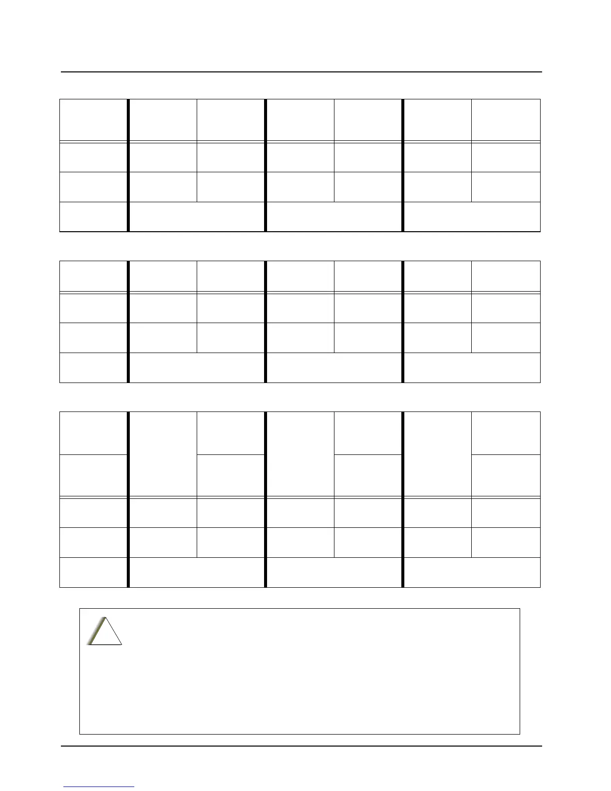
Table 2-1. Dash O2, O3, O5, O7 or O9 Radio Operations Dependent Upon A+ and Ignition Connections
Dash Mount
Transceiver
Red Power
Wire
HLN6863
Thin Red Wire
Transceiver
Red Power
Wire
HLN6863
Thin Red Wire
Transceiver
Red Power
Wire
HLN6863
Thin Red Wire
Connected to
battery
XXX X
Connected to
ignition switch
XXX
Ignition switch
controls
No ignition switch control. Enables ignition switch functionality
as programmed in the codeplug.
Illegal wiring configuration. See
CAUTION note.
Table 2-2. Remote O2, O3, O5, O7 or O9 Radio Operations Dependent Upon A+ and Ignition Connections
Remote
Mount
Control Head
Red Wire
Control Head
Yellow Wire
Control Head
Red Wire
Control Head
Yellow Wire
Control Head
Red Wire
Control Head
Yellow Wire
Connected to
battery
XXX X
Connected to
ignition switch
XXX
Ignition switch
controls
No ignition switch control. Enables ignition switch functionality
as programmed in the codeplug.
Illegal wiring configuration. See
CAUTION note.
Table 2-3. Remote O2, O3, O5, O7 or O9 Radio Operations Dependent Upon A+ and Ignition Connections
Mid Power
Dash/Remote
Transceiver
Red Power
Wire
HLN6863
Thin Red Wire
at J2
Transceiver
Red Power
Wire
HLN6863
Thin Red Wire
at J2
Transceiver
Red Power
Wire
HLN6863
Thin Red Wire
at J2
High Power
Dash/Remote
HLN6863
Thin Red Wire
at J626
HLN6863
Thin Red Wire
at J626
HLN6863
Thin Red Wire
at J626
Connected to
battery
XXX
Connected to
ignition switch
XXX
Ignition switch
controls
No ignition switch control. Enables ignition switch functionality
as programmed in the codeplug.
Illegal wiring configuration. See
CAUTION note.
DO NOT connect any wires to the battery terminals until you have finished the entire
radio installation (Dash or Remote Mount) configuration to avoid potential equipment
damage.
Incorrect wiring of the radio may result in incorrect ignition sense detection, incorrect
power-on state, or incorrect power-off state of the radio system.
The Control Head Power cable wire (RED) and Transceiver Power cable wire (RED)
are always attached to the battery terminal and NOT to the ignition switch.
 Loading...


