6878215A01
Options and Accessories Installation Remote-Mount Accessory Installation 4-5
4.2.5 Horn-Ring Transfer
Configure the Horn Relay for either Negative Contact or Positive Contact as shown in section 6.3 of
the siren/PA manual (6881093C18). Program the designated VIP-OUT line for “Horn-Ring Transfer”
and program the designated VIP-IN line for “Horn-Ring”.
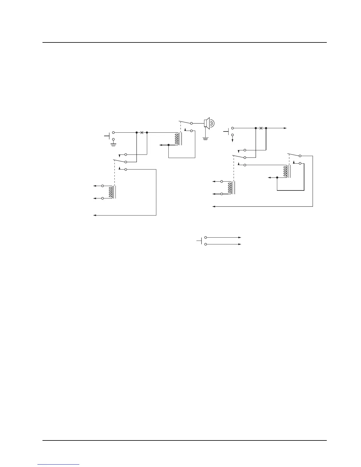
Figure 4-5 shows wiring diagrams for connecting the Horn-Ring via a transfer relay for both negative
and positive ground systems. Refer to the siren/PA manual (6881093C18) for more information.
Figure 4-5. Siren/PA Horn-Ring Connections
4.2.6 Record Audio Out Jack of Transmit and Receive Audio
The use of Power Cable kit HKN6187_ (see Figure 2-47) provides access to both the transmitted
audio speech, as well as the received audio speech. This can be recorded with a standard tape
recorder using a 2.5 mm connector.
4.2.7 Earphone Jack
The use of Power Cable kit HKN6187_ (see Figure 2-47) provides the ability to use a standard
earphone/headset instead of the external speaker. Once a cable is plugged into this 2.5 mm jack, the
external speaker attached at the control head will turn mute.
To Horn
Break
Here
Horn
Ring
To Control Head VIP
Output Programmed for
Horn-Ring Transfer
To Control Head VIP
Input Programmed
for Horn-Ring
To SW B+ at
VIP Connector
N.C.
COM.
N.O.
To DIG. GND at
VIP Connector
+ 12V
Positive-Contact Horn-Ring
Negative-Contact Horn-Ring
Under Hood
Horn Relay
Horn
Break
Here
Horn
Ring
To Control Head VIP
Output Programmed for
Horn-Ring Transfer
To Control Head VIP
Input Programmed
for Horn-Ring
Any SPDT Relay with 12V Coil
and Suitable Contact Ratings for
Vehicle Installation
N.C.
COM.
N.O.
+ 12V
Normally-Open
Momentary
Contact Pushbutton
To VIP Input Programmed for Horn-Ring
To DIG. GND at VIP Connector
Pushbutton Connections
NOTE: Locate Pushbutton
in a Location Convenient to
the Driver
To SW B+ at
VIP Connector
 Loading...


