6878215A01
Options and Accessories Installation Remote-Mount Accessory Installation 4-3
4.2.1 Emergency Pushbutton or Footswitch Installation
Mount the switch using the hardware that comes with the kit. Connect the button/switch wires to a
ground pin and the emergency pin, removing the default jumper wire in the rear accessory cable.
The button/switch will short the pins when in-active. When the button/switch is pressed, its contact
opens, the emergency path is un-ungrounded and pulled-high inside the radio transceiver, and
detected by the processor. If an emergency accessory is used at either (or both) J2 connector and
J626 connector, all jumper wires, shorting emergency to ground, must be removed so button/switch
press can be detected.
In additional to removing the default jumper wires in accessory cables, you must also remove a
jumper part on the printed circuit board of the TIB, in order for the button/switch to be detected. On
the TIB PCB (both mid power and high power use the same TIB) a zero-ohm jumper is placed by
default so that the radio does not go into emergency when no cable is attached at either J2 or J626
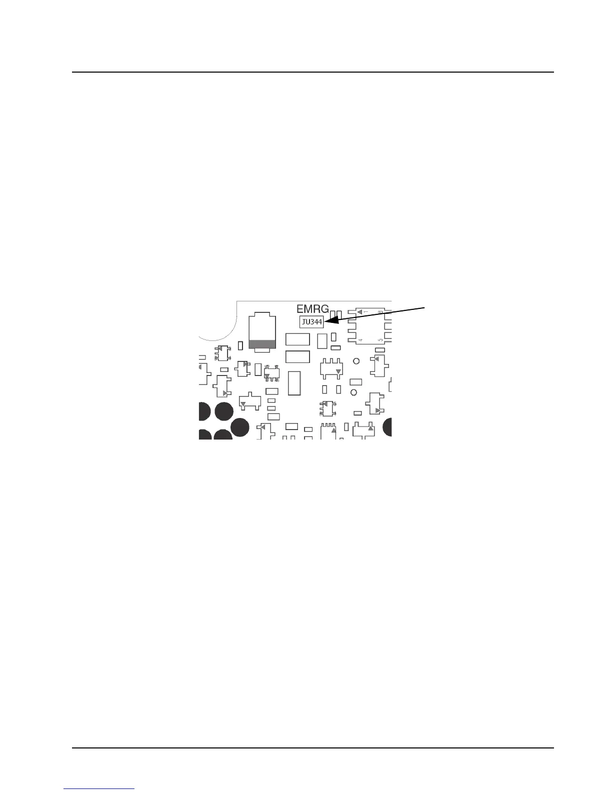
in remote mount configuration. This jumper part, JU344, must be removed if either or both J2 and
J626 will have any type of emergency cable and button/switch attached. Otherwise, the processor
will never see emergency become un-grounded.
Figure 4-3. Emergency Jumper Removal in Remote Mount
1. Turn-off power to the radio system.
2. Detach the TIB from the radio transceiver.
3. Detach the TIB flex.
4. Remove TIB PCB from the plastic housing using TORX T10 screwdriver. Refer to the
disassembly procedure in the Basic Service Manual.
5. Located JU344, See diagram
6. Remove JU344 from the TIB PCB using a soldering gun. Clean off excess solder.
7. Reassemble the TIB following the Basic Service Manual procedure. Use 6-8 in-lbs torque
on each screw. Remember to include the TIB O-ring gasket.
8. Re-attach the TIB flex.
9. Re-attach the TIB to the radio transceiver.
10. Apply 6-8 in-lbs of torque to each screw to secure the TIB to the radio transceiver.
 Loading...


