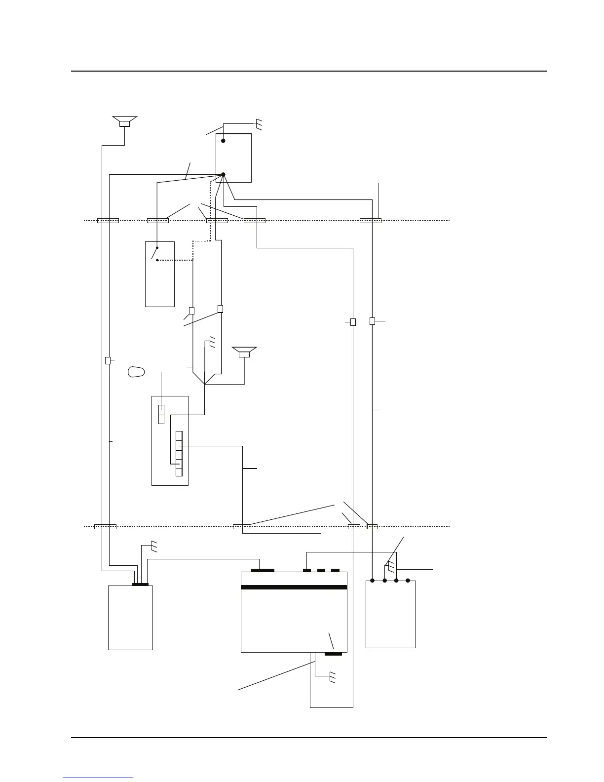
Figure 2-21. Cabling Interconnect Diagram for 09 Remote Mount (URC is optional)
NOTE:
For remote mount configurations, do not supply IGNITION at the radio's rear accessory connector. IGNITION should be supplied according to TABLE 2-2. See TABLE 2-2 for combinations of wiring the
RED and YELLOW cables.
The RED and YELLOW power cables connect to either the vehicle battery or the ignition switch. Connect the RED cable directly to the battery. The receiver operates when the control head is on. Connec
the YELLOW cable to the ignition switch. The transmitter operates only when the ignition switch is on.
Alternate connections: Connecting both RED and YELLOW cables to the battery allows the control head to turn the receiver and transmitter on or off. Connecting both RED and YELLOW cables to the
ignition switch allows the ignition switch to turn the receiver and transmitter on or off. Alternator whine and other noise problems may occur. Isolate the RED cable with a Motorola relay (5900813674).
 Loading...


