2 OVERVIEW
7
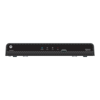
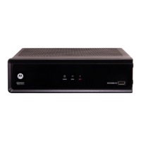
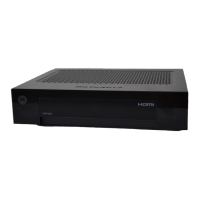
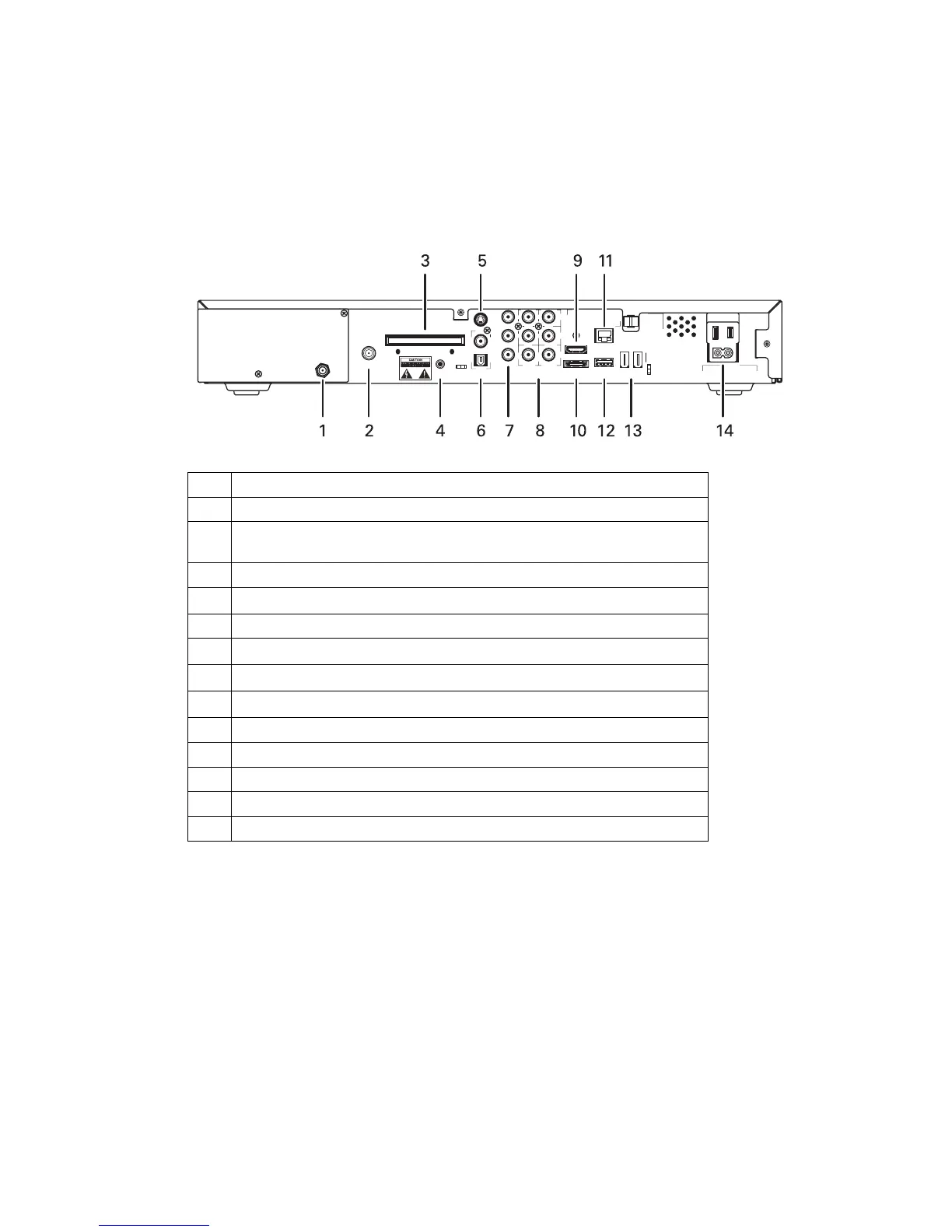
Rear Panel
The rear panel contains a switched power outlet; connectors for video, audio, and RF
cabling; data output; and modem and data interface connectors. Some connectors
are not enabled and require the support of application software.
Figure 2-2 Rear panel
SERIAL
DIGITAL AUDIO
USB
SWITCHED
105 125V
60Hz
4A MAX
500W MAX
-
IEEE 1394
ETHERNET
M Card DEVICE ONLY-
™
S VIDEO-
HDMI
eSATA
Pr
OUT
VIDEO AUDIO/
IN
R
L
V
Pb
Y
RPT OUT
RF OUT
RF1
IN
CM
IN
RF2
IN
CABLE
IN
Table 2-2 Rear panel connections
1 Cable In—Connects to cable signal from your service provider
2 RF Out—Ch 3/4 modulated audio/video (SDTV) to TV or VCR
3 M-Card—Input slot for CableCARD (M-Card device only). If the M-Card
was pre-installed in the factory there will be a cover attached over the slot.
4 Serial—Service only
5
S-Video—Connects to S-Video (SDTV) input of TV or VCR
6 Digital Audio (S/PDIF)—Provides Dolby
®
Digital 5.1 audio or PCM output
7
YPbPr—Component video output (HDTV)
8
Video/Audio—Composite Video (SDTV) /Audio L/R inputs and outputs
9
HDMI—High-Definition TV (HDTV) connector
10 eSATA*—External Serial ATA disk interface
11 Ethernet*—Network connection
12 USB* 2.0—High-Speed peripheral device connection
13 IEEE-1394—Audio and video device connection
14 Power cord connector
*The availability of certain features is dependent upon application support.
 Loading...