CONTENTS
vi
Agile OOB Tuner Hunting.............................................................................31
Summary of Manual Selection of the OOB Frequency (OSD Frequency Override in
Hunted Mode) ........................................................................................31
In-Band Status..............................................................................................32
Unit Address.................................................................................................34
Separable Security.......................................................................................36
Current Channel Status................................................................................38
RF Modem (Upstream) ................................................................................40
Code Modules ..............................................................................................43
Memory Configuration..................................................................................46
Audio/Video Status.......................................................................................46
Interface Status ............................................................................................50
User Setting Status ......................................................................................53
DVR/Hard Drive Status ................................................................................55
DOCSIS Status ............................................................................................57
Application Specific Information ...................................................................60
Interactive Status..........................................................................................61
Keypad—Front Panel Indicators ..................................................................63
5 Troubleshooting ..............................................................................................65
Figures
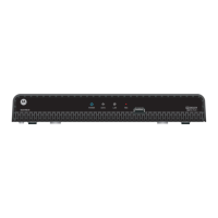
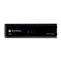
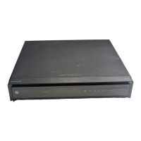
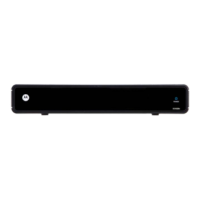
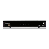
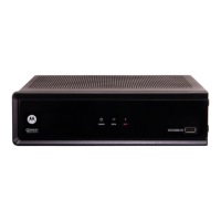
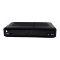
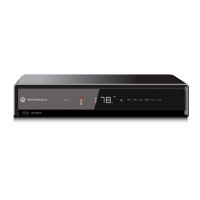
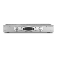
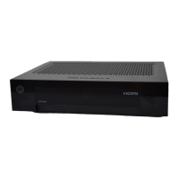
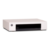
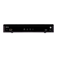
Figure 1-1 Front and rear views.........................................................................1
Figure 2-1 Front panel .......................................................................................5
Figure 2-2 Rear panel ........................................................................................7
Figure 3-1 Cabling to an HDTV..........................................................................14
Figure 3-2 Cabling to an HDTV and an A/V receiver .........................................15
Figure 3-3 Cabling to a Standard-Definition stereo TV ......................................17
Figure 3-4 Cabling an audio receiver.................................................................18
Figure 3-5 Sample data devices you can connect to the DCH6416 ..................19
Figure 4- 1 Example of the Front panel display for the main menu ...................25
Figure 4-2 Example General Status LED (no error)...........................................26
Figure 4-3 Front panel display for Purchase Status diagnostic..........................28
Figure 4-4 Front panel display for the OOB diagnostic......................................30
Figure 4-5 Front panel display for in-band diagnostic........................................33
Figure 4-6 Front panel display of a unit address................................................34
Figure 4-7 Current channel status Front panel displays ....................................39
Figure 4-8 RF upstream modem Front panel display.........................................42
Figure 4-9 Front panel display for code modules...............................................44
Figure 4-10 Interactive status Front panel display .............................................61
 Loading...