Introduction
40 MTS Landmark™ Tabletop Load Units - Product Information
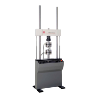
Functional Description
The load unit is a stand-alone testing structure. It consists of the following components:
l Load frame
l Crosshead lifts
l Manifold
l Actuators
l Servovalves
l Accumulators
l Two or more transducers
Load frame
The load frame is the basic structure. Two columns allow a crosshead to be moved up or down to
accommodate different size specimens and fixtures. The crosshead is one of the two reaction masses
in the force train and the base of the load frame is the other. A control panel lets you perform specimen
installation procedures.
Crosshead
The crosshead has the actuator, servovalve, manifold, and accumulators mounted to it. It usually has a
grip or special fixtures attached to the actuator of the crosshead to install one end of the test specimen.
The crosshead can be positioned anywhere along the load frame columns. This lets you test
specimens of different lengths. It can be moved along the column manually or with hydraulic lifts. When
the crosshead is in an appropriate test position, it is manually clamped to that position.
Manifold
The actuator manifold acts as the hydraulic interface between the HPU and the components mounted
to the manifold (actuator, servovalves, and accumulators) of the load unit. It contains the required
hydraulic porting and plumbing to accommodate the various hydraulically controlled components. The
manifold can also control the hydraulic pressure to the load unit.
l Actuator: The linear actuator is located in the middle of the crosshead. It is a hydraulically
powered piston that applies displacement of (or force into) a specimen. It can apply equal
power in tension and compression. One end of the test specimen is installed into a fixture
mounted to the end of the actuator rod.
The rotary actuator is coupled to the linear actuator. It is a hydraulically powered piston that
applies angular displacement of (or torsional force into) a specimen.
l Servovalves: The servovalve regulates the rate and direction of hydraulic fluid flow to and
from a hydraulic actuator. The load unit usually includes a Series 252 Servovalve. Each
actuator requires a servovalve.
l Accumulators: The accumulators suppress line-pressure fluctuations. The load unit includes
 Loading...