System Preparation and Configuration
DS2000 Hardware Manual Section 1: Installing the Cabinet ◆ 1-7
1
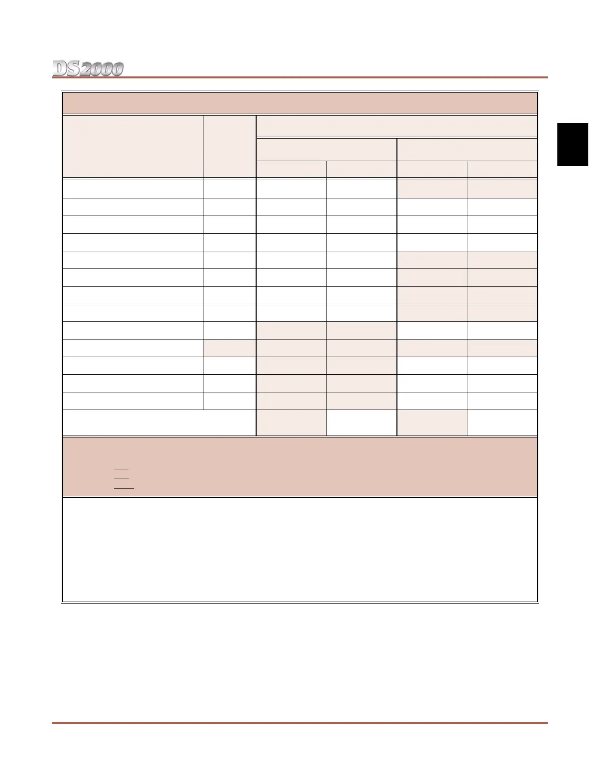
DS2000 System Load Factor Calculations
Description Qty
Load Type
5 VDC 40 VDC
Load Total Load Total
CPU PCB 1 6 6 0 0
16DSTU PCB 3 20
4ASTU PCB 3 5
8ASTU PCB 5 8
4ATRU PCB 4 0
8ATRU PCB 8 0
T1 PCB 8 0
UltraMail PCB (FMS) 19 0
UltraMail 2000 PCB (VMS) 0 5
Telephones (Keysets and SLTs) 0 0
110-Button DSS Console 0 2
24-Button DSS Console 0 1
2-OPX Module 0 3
Item 1: Load Type Totals
(Cannot exceed Item 2: Power Supply Capacity.)
Item 2: Power Supply Capacity
If you have one power supply installed, the capacity is:
If you have two power supplies installed, the capacity is:
If you have three power supplies installed, the capacity is:
5 VDC = 40
5 VDC = 80
5 VDC = 120
40 VDC = 48
40 VDC = 80
40 VDC = 120
Notes:
• A 4 slot cabinet can only have 1 power supply.
• An 8 slot cabinet can have up to 3 power supplies. You cannot have more than two 16DSTU PCBs per power sup-
ply, regardless of System Load Factor calculations.
• Exceeding the allowed Load Type Total (Item 1) will cause the system’s power supplies to automatically shut down
and/or cause erratic system operation.
• Total DSS Consoles installed cannot exceed 4.
• In a 4 slot cabinet, the total of all station, trunk, and UltraMail ports cannot exceed 64.
• In an 8 slot cabinet, the total of all station, trunk, and UltraMail ports cannot exceed 112.
 Loading...