Connecting Extensions
DS2000 Hardware Manual Section 3: Installing Extensions and Trunks ◆ 3-1
3
Section 3: Installing
Extensions and Trunks
Connecting Extensions
Connecting Extensions
Each 16DSTU PCB connects 16 digital extensions. Each 8ASTU PCB connects 8 analog extensions. Each
4ASTU PCB connects 4 analog extensions.
To connect extensions (Figure 3-1):
1. Using Figure 2-12 Connecting Extensions on page 2-10 as a guide, insert the mod jacks into the appro-
priate connector on the PCB.
2. Install a modular jack for each extension within 6 feet of the telephone’s location.
3. For each extension, run one-pair 24 AWG station cable from the cross-connect block to the modular jack.
4. Terminate the station cable WHT/BLU - BLU/WHT leads to the RED and GRN lugs in the modular jack.
5. Back at the main equipment location, run one pair of cross-connect wire between the pins on the B
block and cross-connect block to complete the connection.
6. Install bridging clips as required.
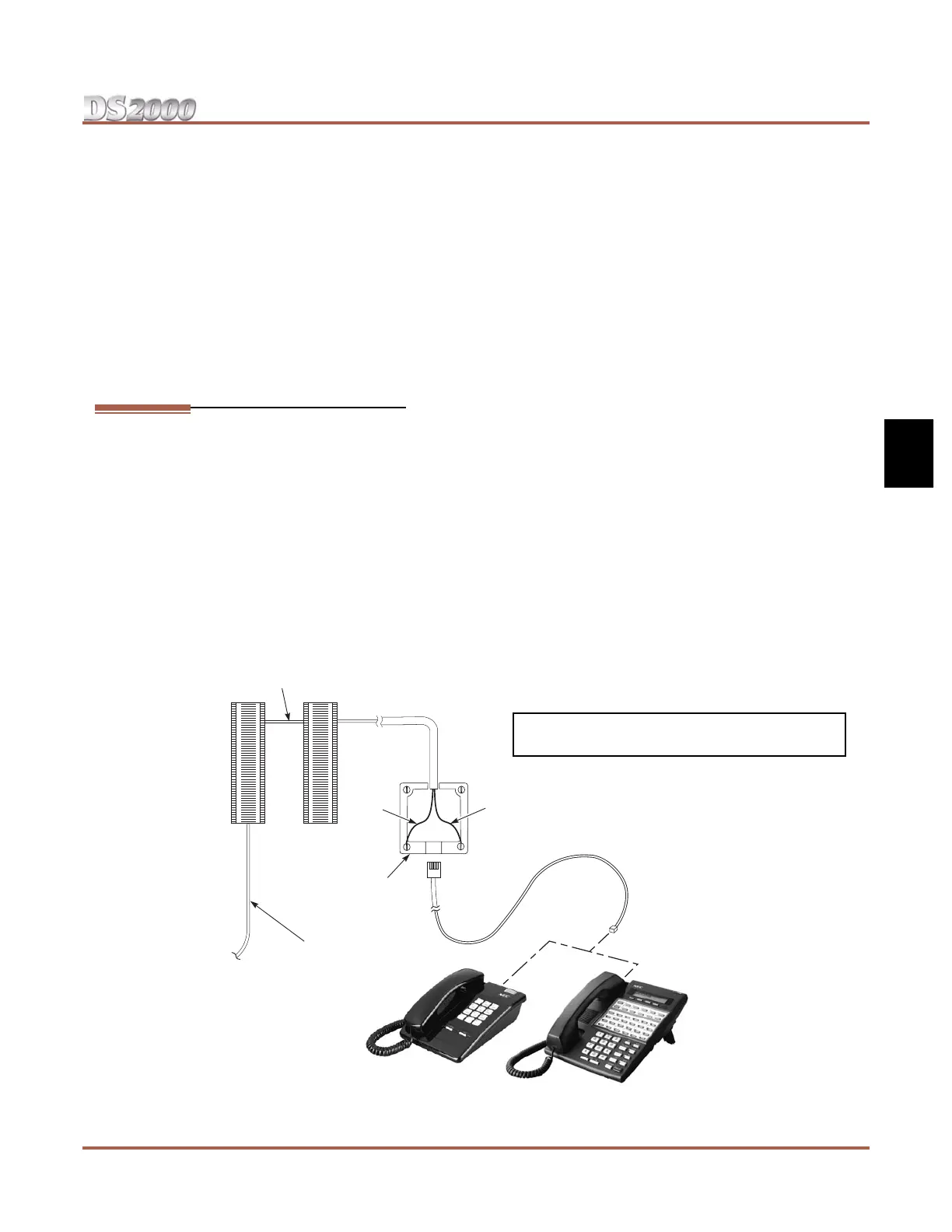
Figure 3-1: Connecting Extensions
625
Modular
Jack
25-Pair
Installation Cable
(P/N 80892)
BLK
YEL
RED
GRN
BLU-WHT
WHT-BLU
Cross
Connect
Block
One-Pair
Cross Connect
Station
Block
80000 - 36A
You can also connect analog extensions to 2-OPX
Modules. Refer to Section 4, Optional Equipment.
 Loading...