Power Failure Telephone
4-4 ◆ Section 4: Optional Equipment DS2000 Hardware Manual
Power Failure Telephone
Power Failure Cut-Through
When AC power fails, the system can automatically cut through to a Power Failure Telephone connection.
To install Power Failure Cut-Through (Figure 4-4):
1. Locate an available 8-pin jack in a trunk (A) block or station (B) block.
Local codes may prevent you from using a DDK connector on the A block for optional equipment.
2. For the 8-pin jack chosen, cross-connect the associated wire pair from the A or B block to the cross-
connect block.
3. Install a modular jack for each Power Failure Telephone within 6 feet of the telephone’s location.
4. For each Power Failure Telephone, run one-pair of 24 AWG station cable from the cross-connect block
to the telephone’s modular jack.
5. Terminate the station cable WHT/BLU - BLU/WHT leads to the RED and GRN lugs in the modular
jack.
6. Install bridging clips as required.
To test the Power Failure Telephone:
1. Connect the power failure telephone. See the illustration below.
2. Power down the system.
3. At the Power Failure Telephone, lift the handset.
You should hear dial tone on the trunk you connected.
4. Place a test call.
If power is restored while a cut-through call is in progress, the call is maintained until the user
hangs up the Power Failure Telephone.
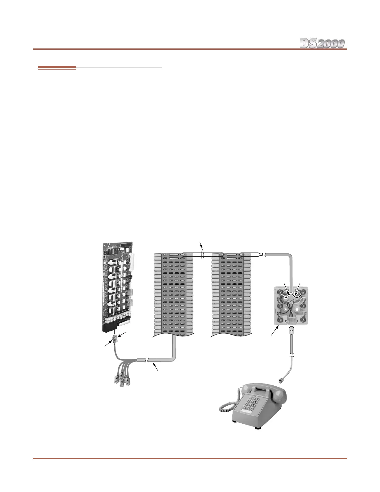
Figure 4-4: Connecting a Power Failure Telephone
80000 - 40
BLK YEL
GRN RED
To Power
Failure
Telephone
connector on
ATRU PCB
Power
Failure
Telephone
25 Pair
Installation Cable
Station
Block
Cross
Connect
Block
8-Pin
Connector
BLU-WHTWHT-BLU
625
Modular
Jack
One-Pair Cross-Connect
 Loading...