Power Up and System LEDs
DS2000 Hardware Manual Section 3: Installing Extensions and Trunks ◆ 3-3
3
Power Up and System LEDs
Power-Up
Now that all the PCBs you need are installed and you have cabled the system, you can now power-up. The sys-
tem will automatically set up the station and trunk PCBs on power up, See
Automatic Slot Configuration on
page 1-4
for more. The system will also automatically set up a station or trunk PCB when you plug it in hot.
You do not need to reattach the right side panel before powering up the system. Leaving the right side panel
removed makes the station and trunk cabling more accessible.
To power up the system (Figure 3-3) through (Figure 3-5):
1. Make sure the system is properly grounded and the PCB bracket is reinstalled and secured.
2. Install a surge protector in the AC outlet you intend to use for system power.
3. Plug the main cabinet’s AC power cord into its surge protector.
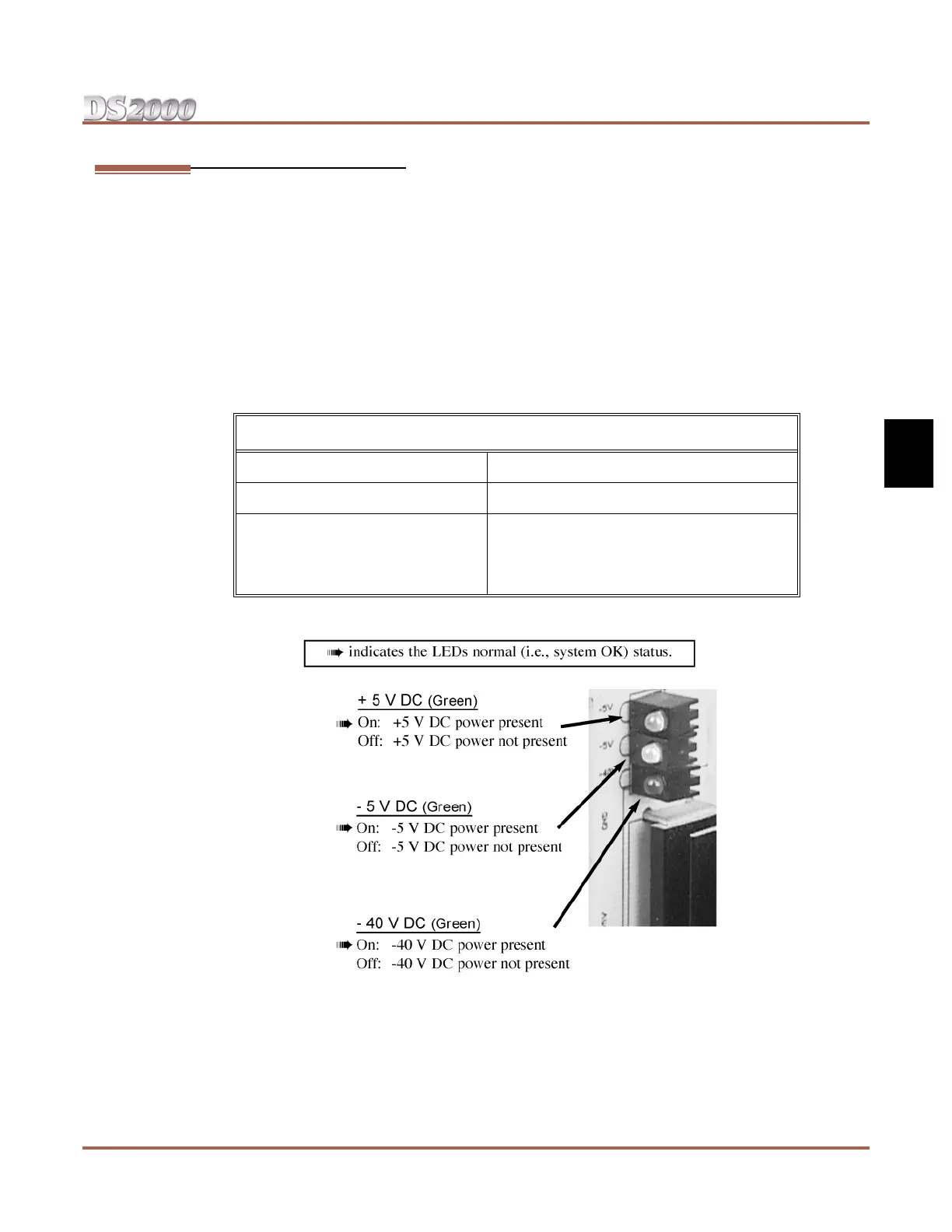
4. Turn on the main cabinet power switch. After about 30 seconds, verify the system LEDs.
5. Verify that the PCBs have successfully powered up.
LED Normal Power-On Status
Power Supply • All three LEDs on (green)
CPU PCB • Top LED flashing (slowly green)
DSTU, ASTU, and ATRU PCBs • Top LED flashing (slowly green)
• Bottom LED flashes (yellow) when ports
on the PCB are busy. The faster the flash,
the more ports are busy.
Figure 3-3: Power Supply Status LEDs
 Loading...