GB
5
GB
2.2) Typical system
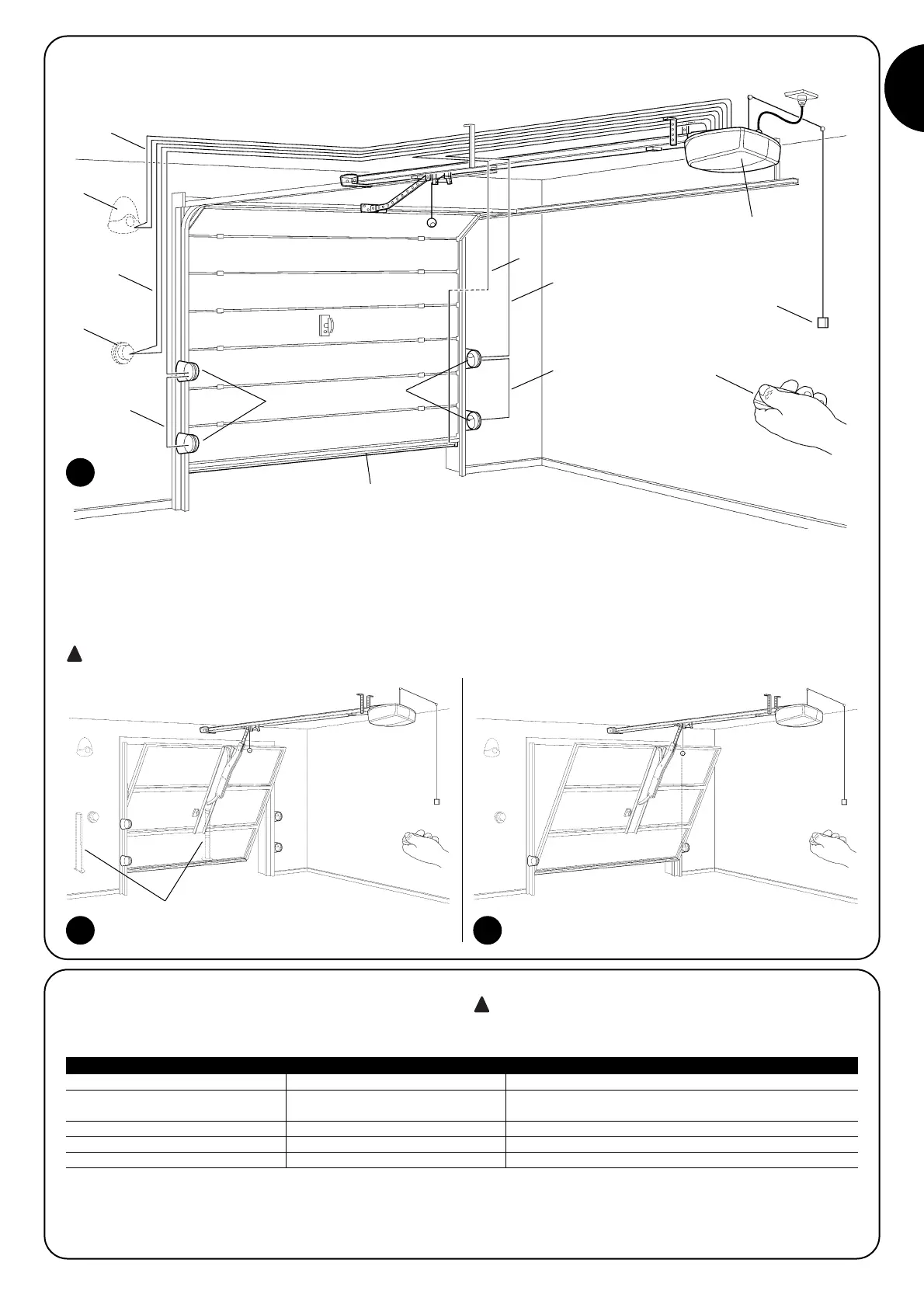
Figure 2 shows a typical system for automating a sectional door.
2
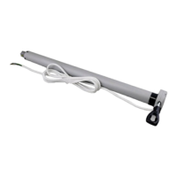
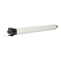
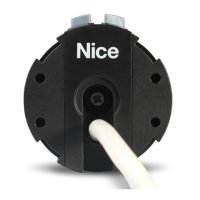
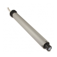
1 SPIN
2 Photocells
3 Photocells on post (fig. 3)
4 Main edge
5 Flashing light with incorporated
aerial
6 Key-operated selector switch
7 PP function cord
8 Radio-transmitter
Figures 3 and 4 show typical installations of a protruding and non-protruding overhead door
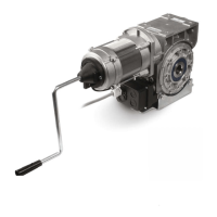
For installations on overhead doors, the accessory SPA5 is required.
3 4
5
6
C
B
A
2
2
4
B
B
D
8
7
1
3
2.3) List of cables
Figure 2 shows the cables needed for the connection of the devices
in a typical installation; Table 6 shows the cable characteristics.
The cables used must be suitable for the type of installa-
tion. For example, an H03VV-F type cable is recommended for
indoor applications
Note 1: A single 4x0.5mm
2
cable can be used instead of two 2x0.5mm
2
cables.
Note 2: Please refer to Chapter “7.3.2 STOP Input” in situations where there is more than one edge, for information about the type of con-
nection
Note 3: Special devices which enable connection even when the leaf is moving must be used to connect edges to the door.
Connection Cable type Maximum length allowed
A: Flashing light with aerial 1 2x0,5mm2 cable 20m
1 RG58 type shielded cable 20m (recommended less than 5m)
B: Photocells 1 cable 2x0,5mm
2
30m
C: Key-operated selector switch 2 2x0,5mm2 cables (noea 1) 50m
D: Primary sensitive edge 1 2x0,5mm2 cable (note 2-3) 30m
Table N°6: list of cables
 Loading...