10 – ENGLISH
3.7 INSTALLING THE GEARMOTOR
a
Incorrect installation may cause serious physical
injury to the person working on the system or to its
future users.
Before starting to assemble the automation, com-
plete the preliminary checks described in the “Pre-
installation checks” and “Product usage limits”
paragraphs.
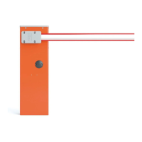
If there is a support surface:
1. remove the upper cover (A) of the boom gate cubicle
2. slide out the rear panel rst towards the other and then out-
wards
A
14
3. place the cubicle on the anchoring surface and mark the
points corresponding to the slots
15
4. move the cubicle and drill the surface through the marked
points
5. insert 4 expansion bolts (not supplied)
6. arrange the cubicle properly and secure it with the appropri-
ate nuts and washers (not supplied).
16
If there is no support surface:
1. dig the hole to insert the foundation plate
Note The anchoring surface must be completely at and
smooth. If the surface is made of concrete, the latter must
be at least 0,15 m thick and must be suitably reinforced
with iron cages. The concrete must have a volume above
0.2 m
3
(a 0.25 m thickness corresponds to 0.8 m
2
, that is,
equal to a square base with sides each measuring roughly
0.9 m). The plate can be anchored to the concrete using
the 4 expansion bolts, equipped with 12 MA screws ca-
pable of withstanding a tensile load of at least 400 kg. If
the anchoring surface is made of a different material, it is
necessary to verify its consistency and whether the four
anchoring points can withstand a load of at least 1,000 kg.
Use the 12 MA screws to fasten the plate.
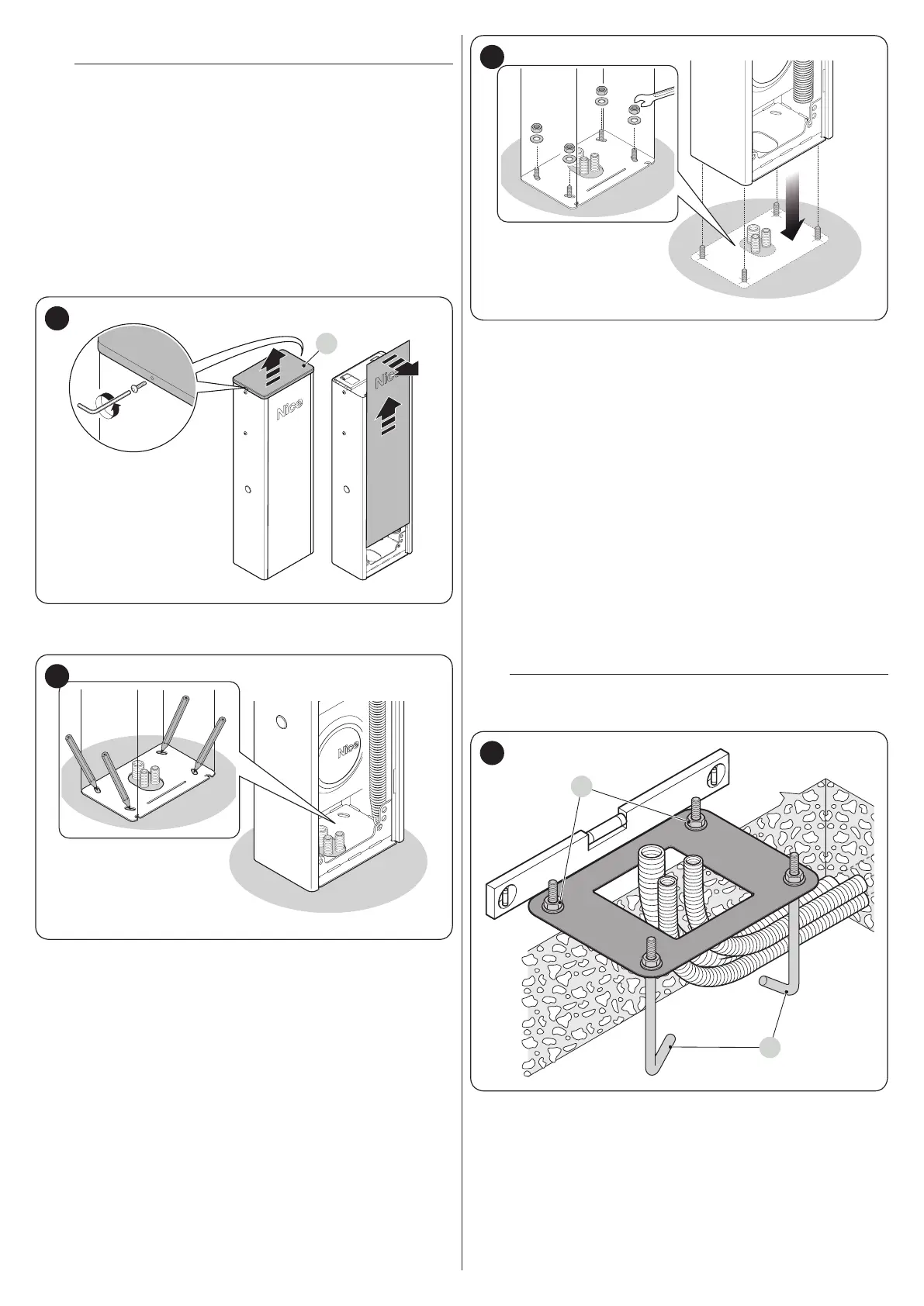
2. arrange the pipes for routing the electrical cables
3. fasten the four anchor bolts (A) to the foundation plate, in-
serting a nut and washer (supplied) on each, on the upper
and lower sides of the plate
m
The lower nut must be screwed up to the end of the
thread.
A
B
17
 Loading...