28 – ENGLISH
8.2 SIGNALS ON THE CONTROL UNIT
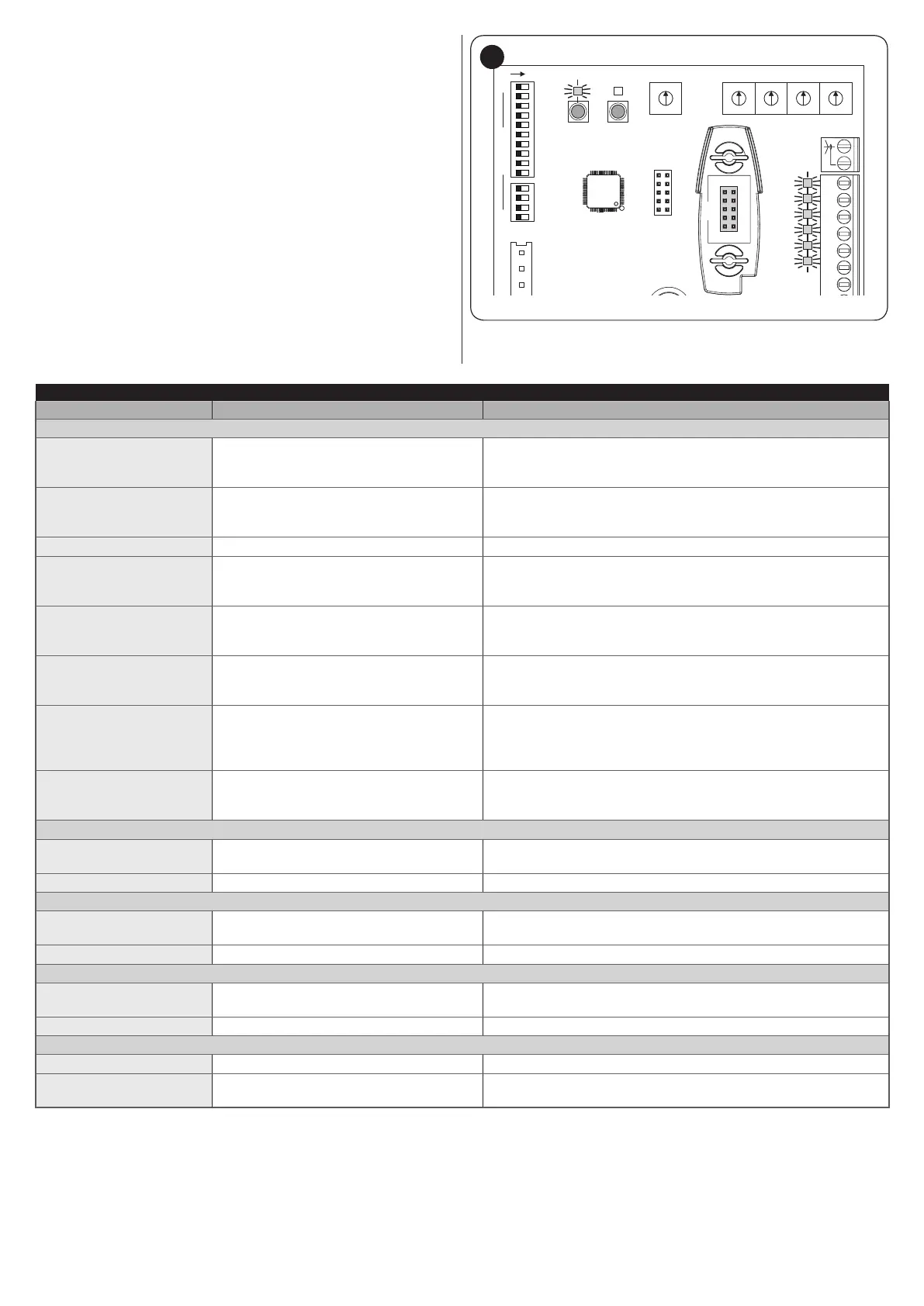
The LEDs near the control unit’s terminals issue special signals to
indicate both normal operation and any anomalies.
The following table describes the causes and solutions for each
type of signal.
PROG RADIO
Fuse F1A
CL
10
11
12
13
14
15
RX
IBT4N
OP
SbS
PH2
PH
ALT
SWITCH
114
AERIAL
46
Table 11
TERMINAL LEDS ON THE CONTROL UNIT
Status Meaning Possible solution
OK LED
OFF Anomaly
Check for the presence of power; check that the fuses are not
blown; if necessary, identify the cause of the fault, then replace the
fuses with other fuses having the same specications.
On Serious anomaly
There is a serious anomaly; try switching off the control unit for a
few seconds; if the condition persists, it means that there is a fault
and the electronic circuit board must be replaced.
1 ash per second Everything normal Normal control unit operation.
2 fast ashes
1-second pause
2 fast ashes
Intervention of a photocell
At the start of the manoeuvre, one or more photocells are blocking
the movement; check whether there are any obstacles. During the
manoeuvre, this is normal if an obstacle is present.
3 fast ashes
1-second pause
3 fast ashes
Obstacle along the travel between one limit
switch and the other
During the gate’s movement, the motors encountered more
resistance. Verify the cause and increase the motor force if
necessary.
4 fast ashes
1-second pause
4 fast ashes
Intervention of the ALT (STOP) input
At the start of the manoeuvre or during the movement itself, the
ALT (STOP) input intervened. Identify the cause.
5 fast ashes
1-second pause
5 fast ashes
The manoeuvre does not start or stops due
to a hardware problem in the motor control
stage
Wait at least 30 seconds then try giving a command and
disconnect the power supply if necessary. If the condition persists,
there may be a serious malfunction and the electronic board
needs to be replaced.
6 fast ashes
1-second pause
6 fast ashes
The limit operating temperature has been
exceeded
Wait for a few minutes until the temperature drops under the
maximum limit.
STOP LED
OFF
Intervention of one of the devices
connected to the STOP input
Check the devices connected to the STOP input.
On Everything normal Stop input active.
PH LED
OFF
Intervention of one of the devices
connected to the PHOTO input
Check the devices connected to the PHOTO input.
On Everything normal Photo input active.
PH2 LED
OFF
Intervention of one of the devices
connected to the PHOTO2 input
Check the devices connected to the PHOTO2 input.
On Everything normal Photo2 input active.
SbS LED
OFF Everything normal Step-by-Step input inactive.
On Intervention of Step-by-Step input
It is normal if one of the devices connected to the Step-by-Step
input is active.
 Loading...