18 – ENGLISH
6 FINAL CHECKS AND START-UP
5.2 ADJUSTMENT OF THE MECHANICAL STOP
POSITIONS
The mechanical stop positions must be adjusted (maximum open-
ing and maximum closing).
Check the correspondence between the direction of the manoeu-
vre and the FCC and FCA limit-switch LEDs:
1. unlock the gearmotor with the relevant key provided (refer
to the “Manually unlocking and locking the gearmotor”
paragraph)
2. manually move the boom to the maximum closing position
and check that the FCC LED is OFF and the FCA LED is ON
3. move the boom to the maximum opening position and check
that the FCA LED is OFF and the FCC LED is ON
4. move the boom to 45° and manually lock the barrier mech-
anism
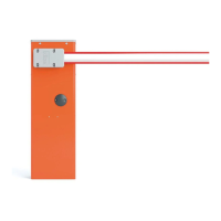
If this does not happen, you need to:
5. power the automation off
6. rotate through 180° the limit switch connector on the control
unit (LIMIT SWITCH)
7. power the automation up.
3
4
5
24V
FCA
FCC
LIMIT SWITCH
MOTOR
24V
180°
34
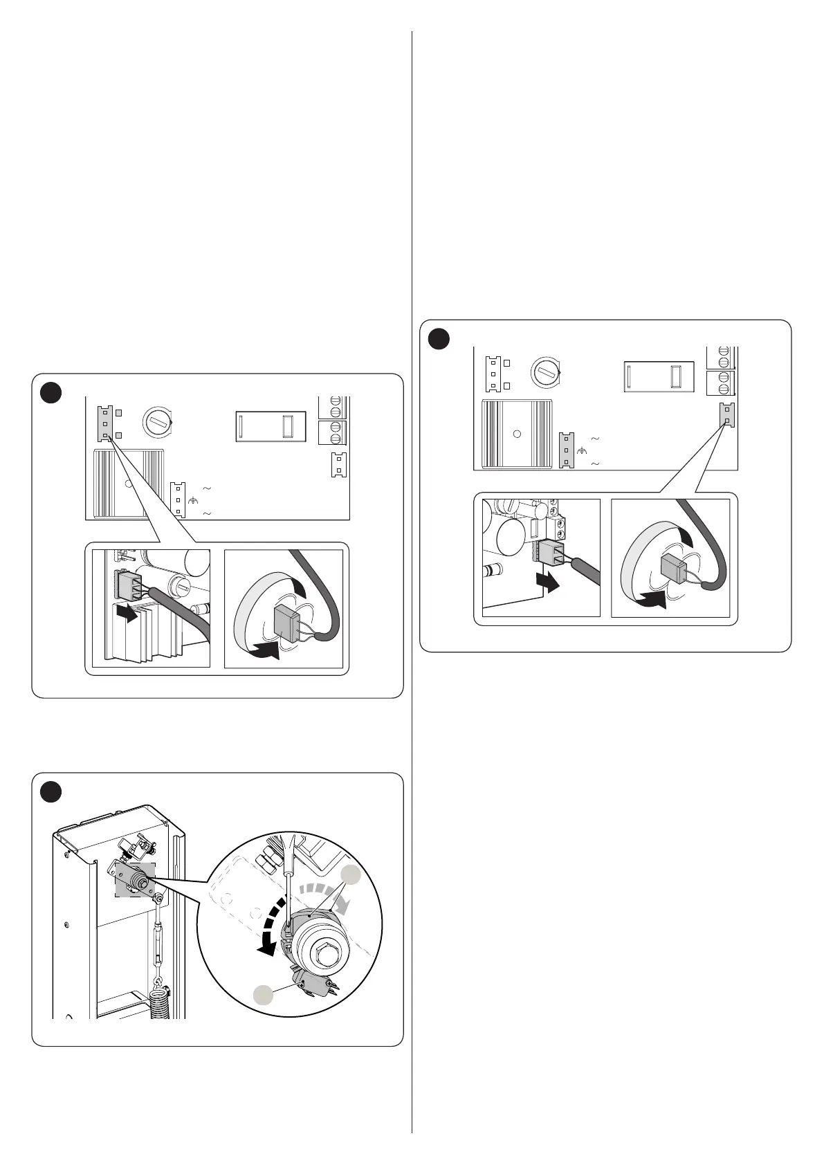
In order to exploit the slowing-down function most effectively, it
is necessary that the limit switch (A) triggers at about 20° before
the mechanical stopping point is reached; if necessary, adjust the
cams (B) to set the desired point.
A
B
35
5.3 CHECKING THE BOOM’S MOVEMENT
Once the limit switch adjustment stage is complete, it is advisable
to carry out a few manoeuvres in order to verify that the barrier
mechanism moves properly.
To do this:
1. set all switches to OFF to have hold-to-run operation
2. with the boom at 45°, give a short control pulse to one of the
devices connected to the Open input (OP - “Figure 32 and
33”) and check that the movement of the boom is in the
opening position
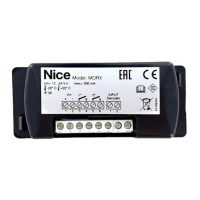
If this does not happen, you need to:
3. power the automation off
4. rotate through 180° the motor connector (MOTOR) on the
control unit
5. power the automation up
6. open and close the door several times to make sure that
there are no defects in the assembly, adjustments or other
faults.
3
4
5
24V
FCA
FCC
LIMIT SWITCH
MOTOR
24V
180°
36
 Loading...