STEERING SYSTEM
FORM NO. 56043088 / Advenger
™
/ BR 600S, 650S, 700S, 800S - 15
STEERING CHAIN REMOVAL AND TENSIONING
1 Turn the master key switch off and separate the battery pack emergency disconnect (13).
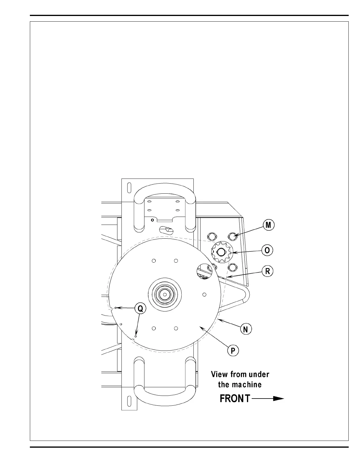
2 See Figure 2. From underneath the front of the machine loosen the (4) (M) Screws and push the lower steering column to the rear of the machine.
This is done to separate the Chain (N) from the Steer Sprocket (O). Service Note: Use a 5/8” socket with 3” extension to loosen screws and
also correctly position the large hole in the Steer Plate (P) in order to access the far back left screw.
3 Remove both Master Links (Q) that secure the chain to the Steer Plate (P) then remove the chain from the chassis.
4 Reassemble parts in reverse order and adjust chain tension so that there is about 3/16”-1/4” (4.7 – 6.4mm) total defl ection with moderate pressure
applied at the Mid-point (R) (as shown). Service Tip Note: Use a pry bar or shims between the chassis and steer column to help secure the
tension adjustment when tightening the (4) steering column mounting screws.
Maintenance
1 Inspect the chain for looseness and binding, re-tension the chain to 3/16”-1/4” (4.7 – 6.4mm) defl ection by following the above adjustment
instructions.
2 Keep all of the steer chain links oiled to prevent excessive wear and binding.
FIGURE 2
 Loading...