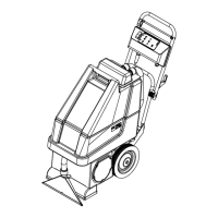
26 - FORM NO. 56043088 / Advenger
™
/ BR 600S, 650S, 700S, 800S
SCRUB BRUSH SYSTEM
FUNCTIONAL OVERVIEW
• Disc Brush System Overview
See Figure 2. The machines Advenger 2400D-3210D and BR 600S-800S use the disc type scrub system. A single 1, 1-1/4 or 1-1/2HP 36V DC
permanent magnet motor is connected at both ends with (2) 90-degree gearboxes that drive the two disc (rotary) brushes.
• Cylindrical Brush System Overview
See Figure 6. The machines Advenger 2400C-3210C and BR 600CS-800CS use two cylindrical brushes that counter rotate to sweep up light debris
and scrub at the same time. Each scrub brush is powered on opposing ends by 3/4 HP permanent magnet motors attached to separate poly-V
belt/pulley drives.
• General Brush Overview
On all models the scrub deck platform is raised & lowered automatically by a vertically mounted electric lift actuator motor (M1). The operation of the
machine’s scrub functions are activated when the operator selects (presses) either the scrub pressure increase or decrease (mode) panel buttons.
The scrub pad or brush pressure ranges (light & heavy) are independently programmable allowing the operator the choice to vary the scrubbing
effort (pressure) while operating the machine. Note: See the Main Control Board Special Program Options section in this manual for more detailed
operation and instructions to change scrub pressure settings.
See Figure 1. The machine’s main scrub system input and output operating functions are regulated (managed) by the combined membrane switch
display panel and main control board E1. The major scrub system functions are…
• Scrub Brush Motor Run Function
To turn On (energize) the K1 brush motor solenoid either the scrub pressure increase or decrease button (location E1 panel) must be pressed and
the (foot activated) drive pedal moved off its neutral position triggering an output from the R1 directional throttle potentiometer. These two-operator
functions deliver the required E1 control board and A1 speed control circuit inputs.
Detailed Explanation of the scrub motor function
A closed E1 membrane panel switch input (either decrease or increase) enables the E1 microprocessor automatic functions for the brush lift, brush
solenoid, solution solenoid, vacuum solenoid and squeegee lift. The next step is the movement of the foot pedal for the needed R1 throttle output
to the A1 speed controller, which causes either FWD or REV motor action. At the moment of R1 throttle input the A1 controller closes an internal coil
driver and outputs a POS. 36V signal from pin #6 (wire color Red/Blk) to the E1 J4-10 connection. This input signal causes the controller to output
a NEG. 36V signal from J2 pin #1 (wire Wht/Red) that energizes the K1 brush motor solenoid coil pulling in the high current contactor making the
brush motor(s) turn on (run).
• Scrub Brush Actuator Lift Motor Function
The control board outputs activate (raise and lower) the scrub-deck for installing, removing and controlling the scrub brushes’ selected current load.
The negative (-) brush motor wire is specially designed so that it has a known (specifi ed) resistance value. As brush motor current passes through
the negative wire that is, in effect, a low value resistor, a small voltage is measured across it which is proportional to the motor current. This current
measurement circuit (shunt) is made up of two small diameter sense wires (J4-12 Yel/Vio & J4-8 Blk) and are the inputs used by the control board
to calculate the exact current level of the scrub brush motor. Any temperature change to the large (Neg.) motor wire affects its resistance so the
circuit temperature is sensed by a thermistor (*) built into the control board. This allows the controller to provide a level of error correction for the
temperature resistance changes. When the controller senses a current draw out of the desired range it automatically turns on the M1 actuator
motor to raise or lower the scrub deck. This process is on-going in maintaining the operator’s selected scrub motor current load (PA #) to sustain
the desired brush working pressure.
• Low Voltage Cut-Out Function
The purpose of the low voltage cutout function is to help prolong battery life. The main control board E1 is programmed to monitor the machine’s
battery pack voltage to prevent over discharging of the batteries. The brush motors, brush lift actuator and solution solenoid valve will turn OFF
automatically and cease to function when the batteries are discharged to the selected cutout level. The cutout level is adjustable between two settings.
The standard battery type (wet cell) is 31.5 volts (1.75 volts per cell) and maintenance free battery (gel) is 33 volts (1.83 volts per cell). Note: See
the Electrical System for instruction in selecting (setting) the two different thresholds.
* Thermistor: A special semiconductor resistor whose resistance value varies with temperature.
Note: See the “Know Your Machine” section in this manual for a complete explanation for all scrub system operational modes.
 Loading...