SCRUB BRUSH SYSTEM
FORM NO. 56043088 / Advenger
™
/ BR 600S, 650S, 700S, 800S - 33
1/4"
(6.3mm)
AS
AT
A
B
C
SCRUB BRUSH REMOVAL AND INSTALLATION (CYLINDRICAL)
SIDE SKIRT MAINTENANCE & ADJUSTMENT (CYLINDRICAL)
General Overview: The side skirts function is to channel the wastewater to the rear pick-up squeegee, helping contain the water within the machine’s
cleaning path. During normal use the blades will wear in time. The operator will notice a small amount of water leaking out underneath the side
skirts. The skirt height adjustment is automatic on this system using spring tension and movable linkage arms to control the blade pressure. The
side skirt assemblies must move up and down freely for proper operation.
To replace the scrub system side skirts…
• See Figure 6. Remove the (2) Hairpins (AM) and swing the skirt assemblies open. Remove the (AR) Screws and nuts then remove the skirts
and replace.
To adjust the scrub system side skirts…
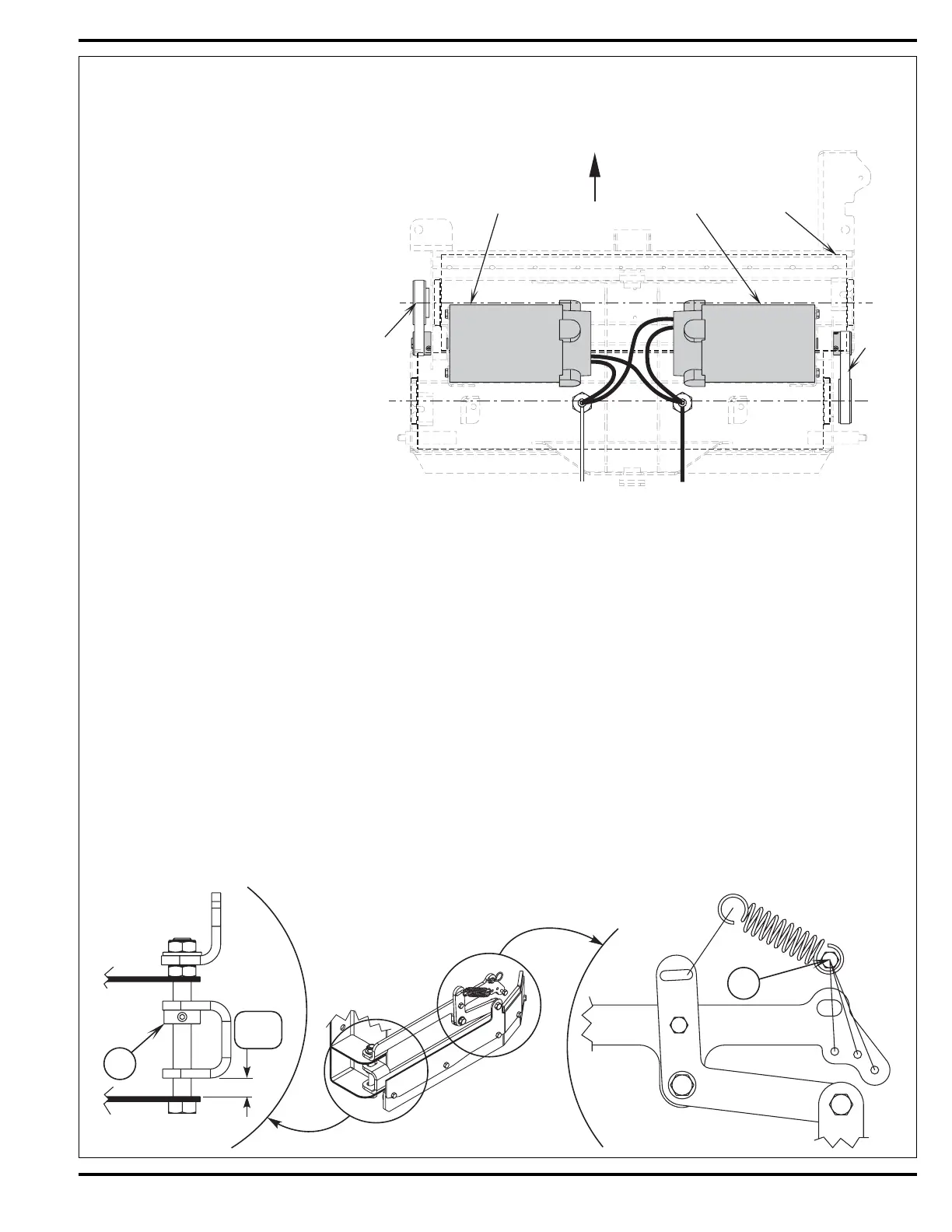
Note: The side skirt blade assemblies have two minor adjustments, they are the individual front collar height and the rear blade pressure spring.
See Figure 9. The Stop Collar (AS) is installed on the pivot hinge bolt to help control the front skirt mount bracket’s travel when the scrub deck is
lowered. It limits the front of the blade from folding (curling) under when scrubbing. Thus allowing the blade to hold its shape better, reduce blade
damage and wear.
A limited amount of adjustment for general blade wear and squeegee wiping performance can be made by reinstalling the spring attachment Screw
(AT) into a different mount hole (A, B or C). This change will increase or decrease the spring force (pressure) pulling down on the rear edge of the
skirt blade. Position “C” creates maximum down pressure on the blade and position “A” is minimum pressure.
1 Make sure the key switch is off and
disconnect the battery pack before
servicing.
2 To access the brushes, swing open both the
side skirt assemblies. See Figure 6. Note:
The skirts are held in place by Hairpins (AM)
on each side, remove the pins and swing
the skirt assemblies out of the way.
3 Loosen the black knobs (one on each side)
that secure the removable bearing idler
support Plate (AQ) to the brush housing,
then pull the plates down and out to remove.
Grip the scrub brush then pull and slide it
out from the housing end.
4 To install the brush slide it into the housing,
lift slightly, push and turn until it seats into
the drive end assembly.
5 Re-install the idler end plate assemblies,
close the skirt assemblies and secure with
the hairpins.
FIGURE 8
FIGURE 9
FRONT
Belt
Brush
Right MotorLeft Motor
Belt
+
BLKBLUE
CCW Rotation
from shaft end
CCW Rotation
from shaft end
 Loading...