SCRUB BRUSH SYSTEM
FORM NO. 56043088 / Advenger
™
/ BR 600S, 650S, 700S, 800S - 27
SCRUB BRUSH SYSTEM TROUBLESHOOTING
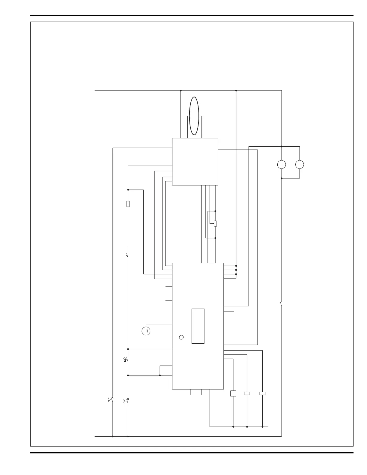
On all models (disc & cylindrical) the scrub system’s major electrical components are monitored by the main controller (E1) to detect any system
function failures (error codes). The system components covered are the brush motor(s) (M7 & M8), brush solenoid (K1) and brush lift actuator motor
(M1). Detected error codes from the main controller are displayed on the hour meter LED display (G) as they occur. Note: Reference the Main Control
Board Troubleshooting Guide in the Electrical System of this manual for specifi c fault descriptions and service repair actions.
FIGURE 1
M7
MOTOR, BRUSH
Amps = 22
M
K1
CONTACT N.O.
K2
S2
M8
M
K1
CONTACTOR , BRUSH
Amps = .33
M1
BRUSH LIFT
ACTUATOR
Amps = 3
M
F2
To Wheel Drive Motor
L1
S1
F3
F4
R1
POT. 5K OHM
1
2
3
RED
BLK
RED
RED
BRN/YEL
BRN/YEL
BRN
RED/W HT
ORN/BLK
GRA
VIO
BLU/BLK
RED/BLK
BRN/BLK
BLK
WHT/BRN
WHT/BRN
BRN/WHT
WHT/RED
WHT/RED
RED
BLK
YEL/VIO
BLK
BLU
BLK
BLU
YEL/VIO
BLK
BRN/WHT
BRN
ORN
ORN
ORN/BLU
ORN
VIO
YEL
YEL
B+ 1
B+ 2
KEY SW.
SEAT SW.
POT. OUT
POT. IN
REV.
FOR./ REV.
PIN 13 -- POT. LO
PIN 3 -- POT. HI
PIN 4 -- POT. WIPER
PIN 16 - REV. ALARM
PIN 6 -- BRAKE
B+
B-
M2
M1
PIN 8 -- SLOW/FAST
ACC
BRUSH
B- 1
B- 2
B- 3
B- 4
A1
SPEED CONTROLLER
INTERFACE
THERMISTOR
I -- BRUSH
E1
CONTROL BOARD
SPEED LIM IT
J4-8
J2-5
J3-5
J3-6
J4-12
J4-2
J2-1
J2-8
J2-7
J2-6
J2-10
J3-1
J3-4
J4-11
J4-10
J4-4
J4-9
J4-3
PIN5 -- KSI
STATUS
J4-5
PIN9 -- STATUS
J2-9
PIN 18 -- SPEED LIMIT
GND
MOTOR, BRUSH
Amps = 22
+
+
+
12
 Loading...