12 - FORM NO. 56043107 - Advolution
™
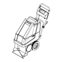
2710
/ UHR 70-1700
FUNCTIONAL DESCRIPTION OF CONTROL BUTTONS:
Key Switch (AA) – Main Power Switch, when turned on controls battery input to machine’s main control board and wheel drive speed control.
Battery Condition Indicator (BB) – The Battery Condition Indicator will give an indication of the state of charge of the batteries. Three lights
make up the Indicator Display (Red-Yellow-Green). See the electrical system in this manual for discharge percentage details of each indicator
light.
Hour Meter/Error Display (CC) The 5-character display on the I/O Panel is primarily used as a display for the hour meter function. When the Key
Switch (A) is activated pad pressure setting 1,2, or 3 will appear briefl y in the right corner of the display. Followed by fi ve 8’s to show functionality
of the L.E.D. Display, then switching to hours on the unit. This display is also used to display the following information depending upon which
mode the control is in:
• Error Codes*
• Pad Pressure Settings (1,2, and 3)
• Display of control system default parameters*
*Service Note: Have a qualifi ed Service Technician reference the Service Manual for explanations about Error Codes and Control Fault + Parameter Changes. A
description of Error Codes can be found in the electrical section of this manual
Pad Drive Indicator Light (DD) –
• Indicator will be blank (off) when deck is in the raised position.
• Indicator will be light Green when lowering the deck as the pad drive raise-lower switch is activated.
• Indicator will be dark Green when the Drive Pedal is engaged in Forward or Reverse activating the pad motor.
• Indicator will be Red when raising the deck as the pad drive/raise-lower switch is activated.
• At full raised position the Red light will go out.
Pad Drive Raise-Lower Switch (EE) – Pressing this switch will activate (turn on) the Lower/Raise burnishing deck lift actuator functions – see
indicator lights description for further information.
Horn Indicator Light (FF) – Indicator Light will turn Green when Horn Switch is depressed. And also displays fault fl ash codes. NOTE: See
electrical system Curtis Control diagnostics in this manual.
Horn Indicator Switch (GG) – Pressing this switch will activate (turn on) the horn, causing a horn like sound to emanate from the machine.

 Loading...