FORM NO. 56043107 - Advolution
™
2710 / UHR 70-1700 - 13
BURNISHING SYSTEM
FUNCTIONAL OVERVIEW
The machines: Advolution 2710 / UHR 70-1700 (Model numbers 56422000, 56422001 & 56411002) use the disk type burnishing system. The pad
driver assembly is directly attached to a single 3.25hp – 36v DC permanent magnet motor.
The burnishing deck is raised and lowered by a horizontally mounted electric lift actuator motor. The operation of the machine’s burnishing
functions are activated when the operator presses the main I/O Panel’s pad drive raise/lower switch (EE). NOTE: See the Electrical System-
Advolution programming modes section of this manual for more detailed operation and instructions to change the burnishing pad pressure setting.
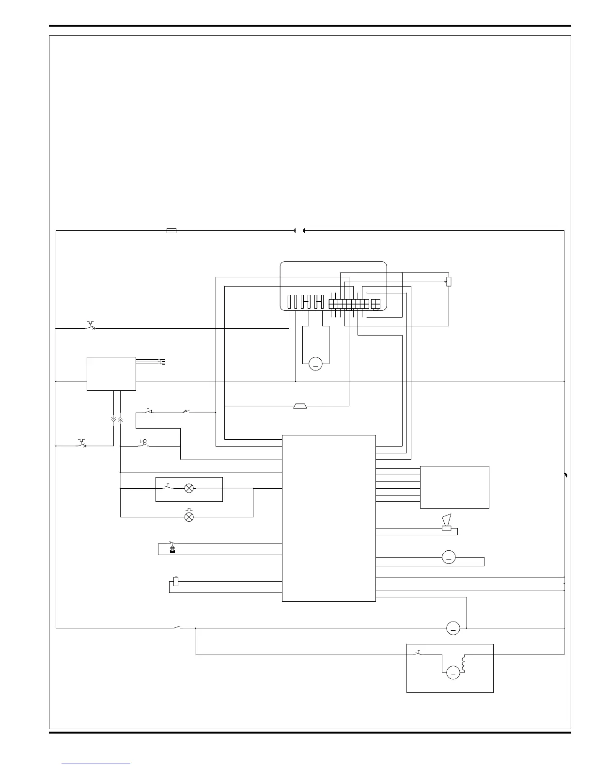
The machines main burnishing system input and output operating functions are regulated (managed) by the I/O Panel and the Control Box. For
the Pad motor to function the operator must turn on (energize) the (K1) pad motor solenoid by pressing the Pad drive Raise/Lower switch (EE) on
the I/O Panel and press the drive pedal moving it off it’s neutral position. These two operator functions deliver the required (A1) Speed control and
Control Box circuit inputs and outputs for the burnishing operation. NOTE: See troubleshooting (page 22) section for more details.
BLK
RED
RED/GRN
YEL/BLK
BLK
GRN/WHT
BRN/BLK
GRA
VIO/BRN
RED
GRN
RED/WHT
ORN
RED/WHT
VIO/BRN
RED RED
WHT/RED
GRNVIO
VIO
VIO
VIO
WHT/ORN
WHT/ORN
WHT/BRN
WHT/BRN
GRN/BLK
GRN/BLK
ORN/BLK
ORN/BLK
GRA/BLK
VIO/BLK
GRA/WHT
BRN/WHT
ORN/BLU
BLK/WHT
BLU/WHT
RED BLK
BLK/YEL
RED
BLK
BLK
RED/WHT
BLKWHT
VIO
RED BLK
BLK
BLK/GRA
BLU
PINK
ORN/WHT
BLU/BLK
BRN
YEL/WHT
YEL/WHT
GRNYEL
WHT/ORN
J2-4 (ACC (-))
J3-1 (B+)
J3-9 (SEAT SW)
J3-2 (KEY SW)
J3-10 (F/R)
(MODE) J2-2
(STATUS) J3-4
I/O PANEL
(B-) J2-10
(B-) J3-8
(SENSE) J3-3
(ACT 1) J2-12
(ACT 2) J2-6
(HORN +) J2-7
(HORN -) J2-1
J2-11 (PAD CONT +)
J2-5 (PAD CONT -)
J3-7 (INTERLOCK B-)
J3-5 (INTERLOCK)
CONTROL BOX
ON-BOARD
BATTERY CHARGER
(OPTIONAL)
56015612 REV. F
(B-) J2-9
J4-6 (PAD SW)
J4-1 (SDA)
J4-2 (SCL)
J4-3 (+5 V)
J4-5 (B-)
J4-4 (HORN SW)
(PAD SW) J1-6
(B-) J1-5
(+5 V) J1-3
(SCL) J1-2
(SDA) J1-1
(HORN SW) J1-4
(REV) J3-6
M
M2
MOTOR, PAD
M
M2
MOTOR, PAD
-+
K1K1
1 2
PLUG AC MALEPLUG AC MALE
S5
SW SPST
S5
SW SPST
1 2
CB2
CIRCUIT BREAKER, 40 AMP
CB2
CIRCUIT BREAKER, 40 AMP
1 2
H1
HORN/BACK-UP ALARM
H1
HORN/BACK-UP ALARM
+ -
M
M4
MOTOR, DUST CONTROL VAC
(OPTIONAL)
M
M4
MOTOR, DUST CONTROL VAC
(OPTIONAL)
1 2
R1
POT. 5K OHM
R1
POT. 5K OHM
1
2
3
---
BT1
BATTERY, 36 VDC
---
BT1
BATTERY, 36 VDC
J7J7
1
2
3
4
5
6
7
8
9
10
11
12
13
14
15
16
17
18
S9
SW SPST
S9
SW SPST
1 2
S2
SWITCH, SEAT
S2
SWITCH, SEAT
21
S3
SWITCH, DECK INTERLOCK
S3
SWITCH, DECK INTERLOCK
1 2
LP6
LAMP, FLASHING
(OPTIONAL)
LP6
LAMP, FLASHING
(OPTIONAL)
1 2
Y1
BRAKE
Y1
BRAKE
12
LP5
LAMP, HEAD
(OPTIONAL)
LP5
LAMP, HEAD
(OPTIONAL)
1 2
K1
COIL, RELAY
K1
COIL, RELAY
M
M1
MOTOR, TRACTION
M
M1
MOTOR, TRACTION
- +
F1
FUSE, 150 A.
F1
FUSE, 150 A.
12
A1
CURTIS 1228 SPEED CONTROLLER
A1
CURTIS 1228 SPEED CONTROLLER
B+
B-
M1 (a)
M2 (a)
M1 (b)
M2 (b)
S1
SWITCH, KEY
S1
SWITCH, KEY
1 2
M
M3
ACTUATOR
M
M3
ACTUATOR
- +
S10
EMERGENCY STOP
S10
EMERGENCY STOP
CB1
CIRCUIT BREAKER, 5 AMP
CB1
CIRCUIT BREAKER, 5 AMP
1 2
K1
1
K1

 Loading...