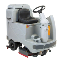
FORM NO. 56043107 - Advolution
™
2710 / UHR 70-1700 - 51
ELECTRICAL SYSTEM
ADVOLUTION PROGRAMMING MODES
Low Voltage Cutout Threshold Selection Mode:
FACTORY DEFAULT: STD
The Advolution is equipped with a low voltage cutout feature to prevent over-discharging the batteries. This feature will automatically shut down
the pad motor when the battery voltage falls to the selected threshold. The cutout level is adjustable. The standard setting is 31.5 volts (1.75 volts
per cell) and the alternate setting is 33.12 volts (1.84 volts per cell). The standard setting should be used unless the battery manufacturer specifi es
the higher cutout voltage. It is important to note that some maintenance free batteries (including some gelled electrolyte cells) are capable of
safely being used with the standard setting. To select between the two types:
1 Press and hold the horn switch while turning the key switch on.
2 Continue holding the horn switch until the status display is scrolling the word “SELECT”.
3 Release the horn switch.
4 Press and release the horn switch twice. The status display should now be scrolling “BATTERY TYPE”.
5 Press and release the pad switch to enter the battery type selection mode.
6 The status display will now show either “STD” or “ALT”. The standard setting has a cutout level of 1.75 volts per cell and the alternate setting
has a cutout level of 1.84 volts per cell.
7 To select the desired option, press and release the horn switch. This will alternate between the two options.
8 To save the setting and exit this mode turn the key switch off.
Fault Detection Enable/Disable Mode:
FACTORY DEFAULT: ON
Normally, the main control unit will perform checks of the electrical system during operation. If a fault occurs in a particular system that system
(and possibly others) will be shut down. This can make troubleshooting the system diffi cult. This option will allow service personnel to disable
some of the fault detection checks to facilitate troubleshooting. This will not disable the over-current protection on any of the systems. To enable or
disable fault checking:
1 Press and hold the horn switch while turning the key switch on.
2 Continue holding the horn switch until the status display is scrolling the word “SELECT”.
3 Release the horn switch.
4 Press and release the horn switch three times. The status display should now be scrolling “FAULT DETECT”.
5 Press and release the pad switch to enter the fault detection enable/disable mode.
6 The status display will now show either “ON” or “OFF” depending on whether the error checking is turned on or off.
7 To select the desired option, press and release the horn switch. This will alternate between the two options.
8 To save the setting and exit this mode turn the key switch off.
Pad Pressure Adjustment Mode:
FACTORY DEFAULT: 1
The amount of pressure applied to the burnishing pad can be adjusted over a limited range by adjusting the pad “pressure” setting in the control
unit. The control unit does not set an absolute pressure, rather it controls the amount of power used by the pad motor which results in a relative
pressure change. The range of adjustment is from a setting of 1 (least pressure) to 3 (most pressure). 1 is the factory default. Having the pressure
setting at 1 will result in the maximum run-time from the batteries. To change the pressure level, perform the following steps:
1 Press and hold the pad switch while turning the key switch on.
2 Continue holding the pad switch until the status display is scrolling the word “ADJUST”.
3 Release the pad switch.
4 Pressing and releasing the pad switch will now scroll through the pad pressure options.
5 Once the desired level is displayed, turn off the key switch to save the setting and exit this mode.
TABLE 2
Pad Motor Pressure Settings & Currents
Pressure Setting Target Current (amps)
170
275
380
 Loading...


