FORM NO. 56043107 - Advolution
™
2710 / UHR 70-1700 - 31
FIGURE 6
WHEEL DRIVE SYSTEM
WHEEL DRIVE MOTOR REMOVAL
WARNING!
Disconnect the battery pack by separating the battery connectors (7) whenever servicing the machine.
1 Follow the Wheel Drive Assembly Removal Instructions.
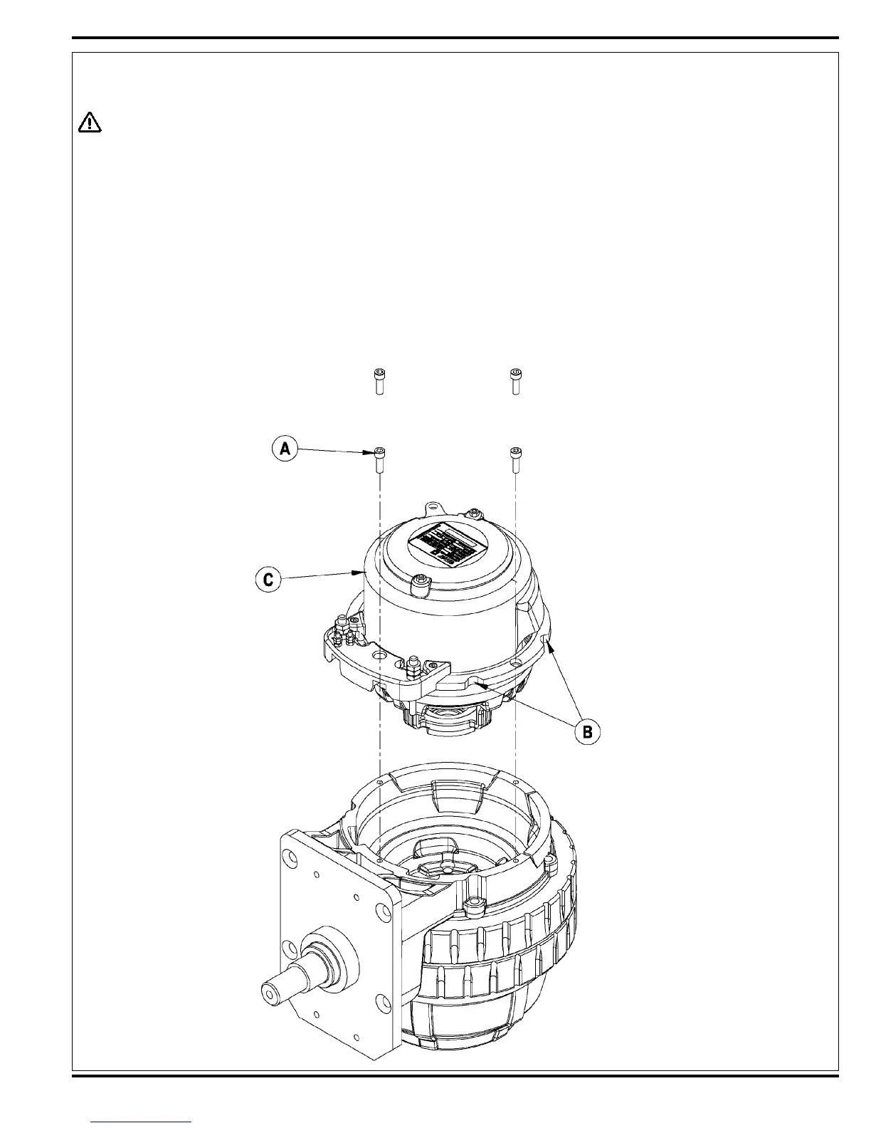
2 See Figure 6. Place motor assembly upright (tire side down) as shown.
3 Remove the (4) Socket Head Cap Screws (A) that secure the electric drive motor to the motor housing casting.
4 Use a hard piece of wood or a brass drift punch to tap the motor mounting fl ange (3 notched locations B) to loosen.
5 Grip the motor / brake end bell (C) and pull the motor up and out of its housing.
6 Inspect the 4 carbon brushes & springs. A new carbon brush measures 3/4”. If less than 1/4” replace.
NOTE: Clean foam fi lters, blow out motor & inspect the oil level in the gear case. Gear case oil is 130GR. Gear case capacity is approx. 4.5 oz.

 Loading...