FORM NO. 56043107 - Advolution
™
2710 / UHR 70-1700 - 43
ELECTRICAL SYSTEM
ACTUATOR DRIVE NUT ADJUSTMENT
This manual section explains the steps for adjusting the drive nut (spring housing) setting for all the pad drive lift actuator motor. Reference the chart below to fi nd
the IN & OUT dimensional specifi cation for an actuator motor needing adjustment.
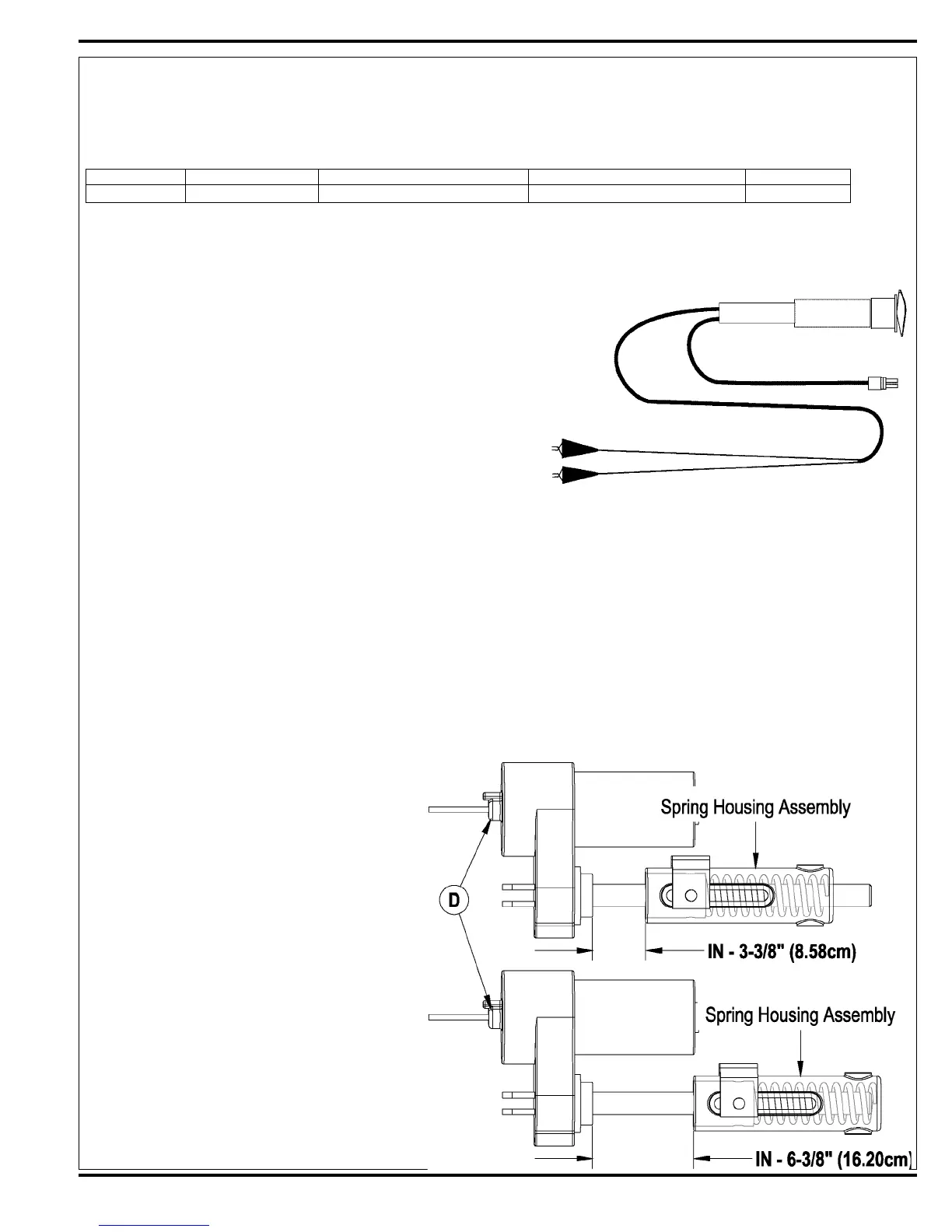
Part # Actuator Motor Spring Housing IN Position Spring Housing OUT Position Models
56393303 Pad Drive Lift 3-3/8”(8.58cm) 6-3/8”(16.20cm) ALL
*The “Spring Housing IN/OUT Position” dimensions are measured when completely assembled. Reference points are the gear box step to the
edge of the Spring Housing Assembly (A) as shown in Figure 4 & 5.
General Instructions
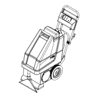
1 See Figure 3. This shows the special actuator power cord adapter (PN
56407502) that is needed to connect the machine’s battery pack and
actuator motor for setting the drive nut limit settings.
2 Open the machine battery compartment and disconnect the battery
connector. The battery pack is needed to power the lift actuator motor to
properly set the IN & OUT limit switches.
3 Connect the actuator motor to be tested to the power cord adapter end.
Then connect the alligator clips from the cord adapter (red clip to the positive
and black to negative) to battery connector or battery posts. The rocker
switch is used to change the motor rotation in setting the correct drive nut
dimension.
FIGURE 3
Instructions for Pad Drive Deck Lift Actuator Drive Nut Adjustment
1 See Figure 4 and 5. On a new pad lift actuator motor fi rst install the Compression Spring (B) then slide on the Spring Housing Guide (A),
followed by the Mounting Hardware (C).
2 Hold onto the spring housing assembly and press the rocker switch to run the drive motor and retract the spring housing towards the motor
housing (its IN limit).
3 Measure the position of the spring housing assembly on the actuator shaft. Manually turn the spring housing assembly to the appropriate IN
position shown in the chart above.
4 Hold the spring housing assembly, then press the adapter cord rocker switch to run the drive motor to the OUT position (wait until the motor
stops).
5 Measure the position of the spring housing assembly on the shaft and compare the measurement with the OUT position shown in the chart.
6 If the measurement doesn’t match the dimension shown in the chart it is necessary to remove the Adjuster Cover (D) and adjust the OUT
position.
7 To increase the travel of the spring housing assembly, turn the adjuster clockwise. To decrease the travel of the assembly, turn the adjuster
counter clockwise.
NOTE: Use a 1/2” (13mm) socket to turn the adjuster.
Each click of the adjuster will change the spring
housing assembly travel 1/16 inch (1.6mm).
8 After each adjustment, hold the spring housing
assembly, run the actuator IN & OUT and check both
dimensions. After checking that the spring housing
limits are set correctly replace the adjuster cover.
Service Tip: Use the above power cord adapter to help
position the spring housing assembly (in or out) for
ease in actuator motor installations.
9 After adjusting the actuator spring housing dimensions,
follow the Pad Lift Actuator Removal And Installation
section to reassemble.
FIGURE 4

 Loading...