48 - FORM NO. 56043107 - Advolution
™
2710
/ UHR 70-1700
ELECTRICAL SYSTEM
FUNCTIONAL OVERVIEW OF MAIN CONTROL BOARD
The primary function of the main control board A1 is to position the burnishing pad with respect to the fl oor surface using a lift actuator motor to
maintain the correct pad pressure and current draw of the pad motor. When the pad drive switch (EE) is depressed this will lower the pad deck to
the operating position and by activating the drive pedal start the pad motor. The controller is continuously monitoring the current to the pad motor
and when it senses a current draw out of the desired range it automatically raises or lowers the pad deck by turning on the pad lift actuator motor.
This process is repeated until the pad motor is shut off. The controller also manages the other supportive systems such as the optional active dust
control. Note: See the Know Your Machine section in this manual for a complete explanation of the machine’s operation.
The secondary function of the main control box is to detect any system failures and display an error code on the display panel or store it in the
main control board’s recall memory mode. The error code(s) are used to help the service person determine the fault and to quickly guide in
repairing a specifi c system malfunction. Note: See the Troubleshooting Guide for further information. An additional special feature of the main
control board is to change program settings for a set of specifi c machine functions. See the Main Control Board Special Program Options section
in this manual for further information.
TROUBLESHOOTING GUIDE
Any error codes detected by main control board will be displayed on the display panel (CC) as they occur. If more than one-error exists the display
will sequence through the error codes at one-second intervals. The error will display as “Err” followed by a two-digit code. EX: Err 06 would be a
Pad Motor Overload.
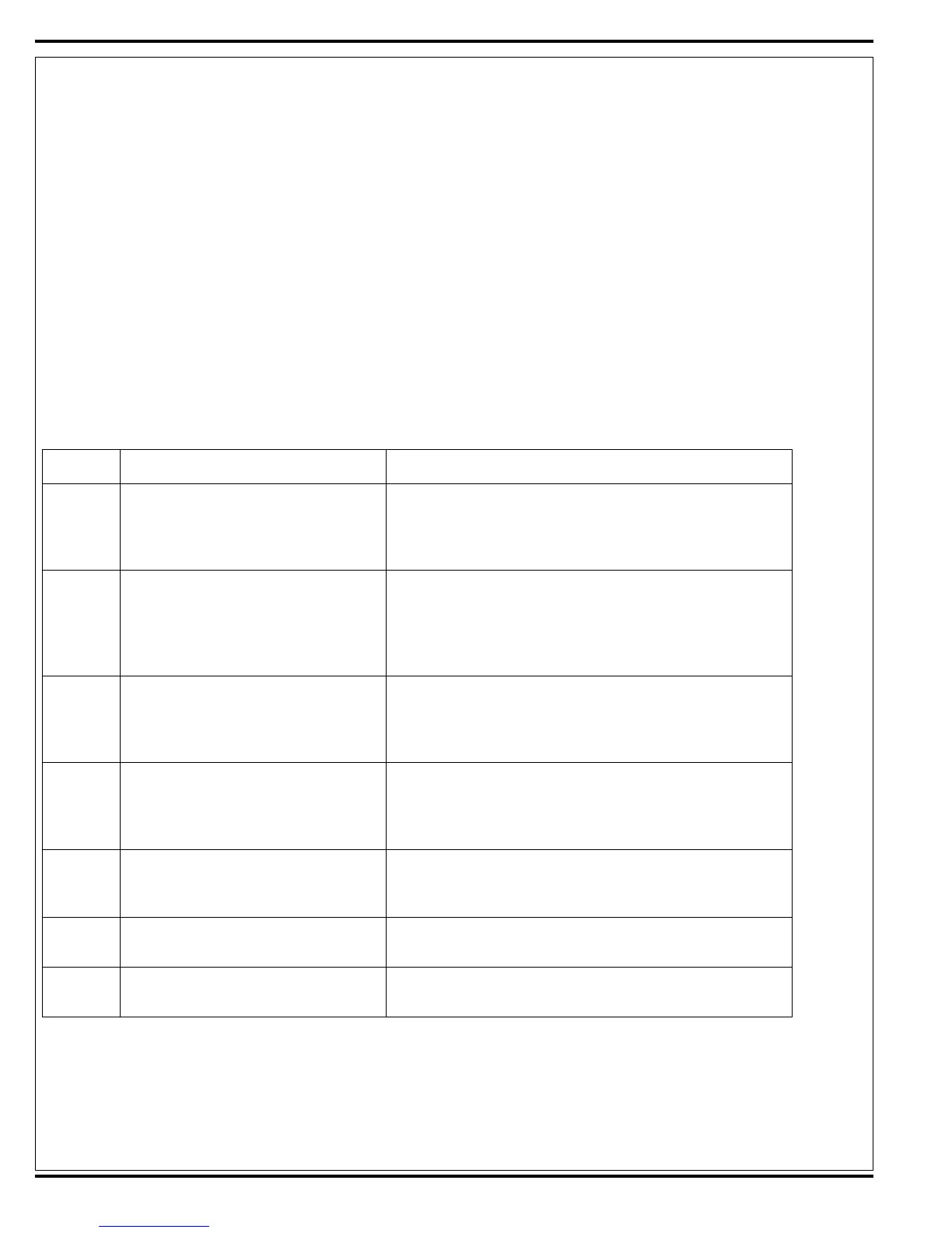
MAIN CONTROLLER ERROR CODES
Display
Code
Fault Description Troubleshooting Action
Err 02 Accessory Circuit Overload Check for a short circuit in the LP5 headlight and LP6 fl ashing
warning beacon accessory systems wiring and components. SVR
Tip: Disconnect each component separately and observe if the code
goes away then check that specifi c component. Repair or replace
defective part or wiring.
Err 03 Speed control System Faults 1. Check for a tripped 40Amp (CB2) breaker and reset if needed. 2.
Next investigate the reason for the mechanical overload. Examples
prolonged ramp climbing, exceeding the machines grad ability limit
and the electric parking brake not releasing. 3. Then see Curtis drive
motor controller section to further troubleshoot the drive system
(table 1).
Err 04 Pad Deck Lift Actuator Motor Overload
Note: Normal current load is1-2.5 Amps,
Max. current load 6 Amps & Max. current no
load 1.4 Amps.
1. Check for binding or frozen lift linkage and excessive weight on
burnishing deck. 2. Perform a current draw test. To test disconnect
the motor plug and attach the actuator test cord (P.N. 56407502) and
compare readings to the fault description table to the left. 3. Test for
short circuits in the actuator motor and wiring. Repair or replace.
Err 06 Pad Motor Overload
Note: See Table #2 burnishing pad pressure
settings in the Pad Pressure Programming
section for detailed load current values for
the three different pressure settings.
1. Check for mechanical binding in the rotation of the pad motor and
also improper pad pressure lift motor operation. 2. check for an open
circuit in the small Black/Yellow pad motor current sense wire and
repair wire if open. 3. Check for short circuit in pad motor or wiring.
Repair or replace.
Err 08 Pad Motor Contactor Coil Open
Note: Coil resistance spec is 120 Ohms
plus or minus 10%.
1. Check for an open circuit in the coil wiring (wire colors Black/White
& Blue/White). 2. Test coil winding resistance, for an open circuit.
Replace if defective. 3. Check controller coil output voltage for 36V if
0V controller failure replace.
Err 17 Pad Lift Actuator Motor Open 1. Check for disconnected actuator wiring, open in wiring or defective
actuator motor. Repair or replace. 2. Check controller actuator output
voltage for 36V if 0V main controller failure (replace).
Err 21 Pad Motor Open 1. Check for open circuits in the pad motor and wiring. Repair or
replace. 2. Test for 36V at the K1 load contact output (red wire #2)
with its coil energized if 0V replace the K1 contactor.

 Loading...