Specifications & Approvals
8 AFP-2800/2802 Manual – P/N 11249 11-Mar-08
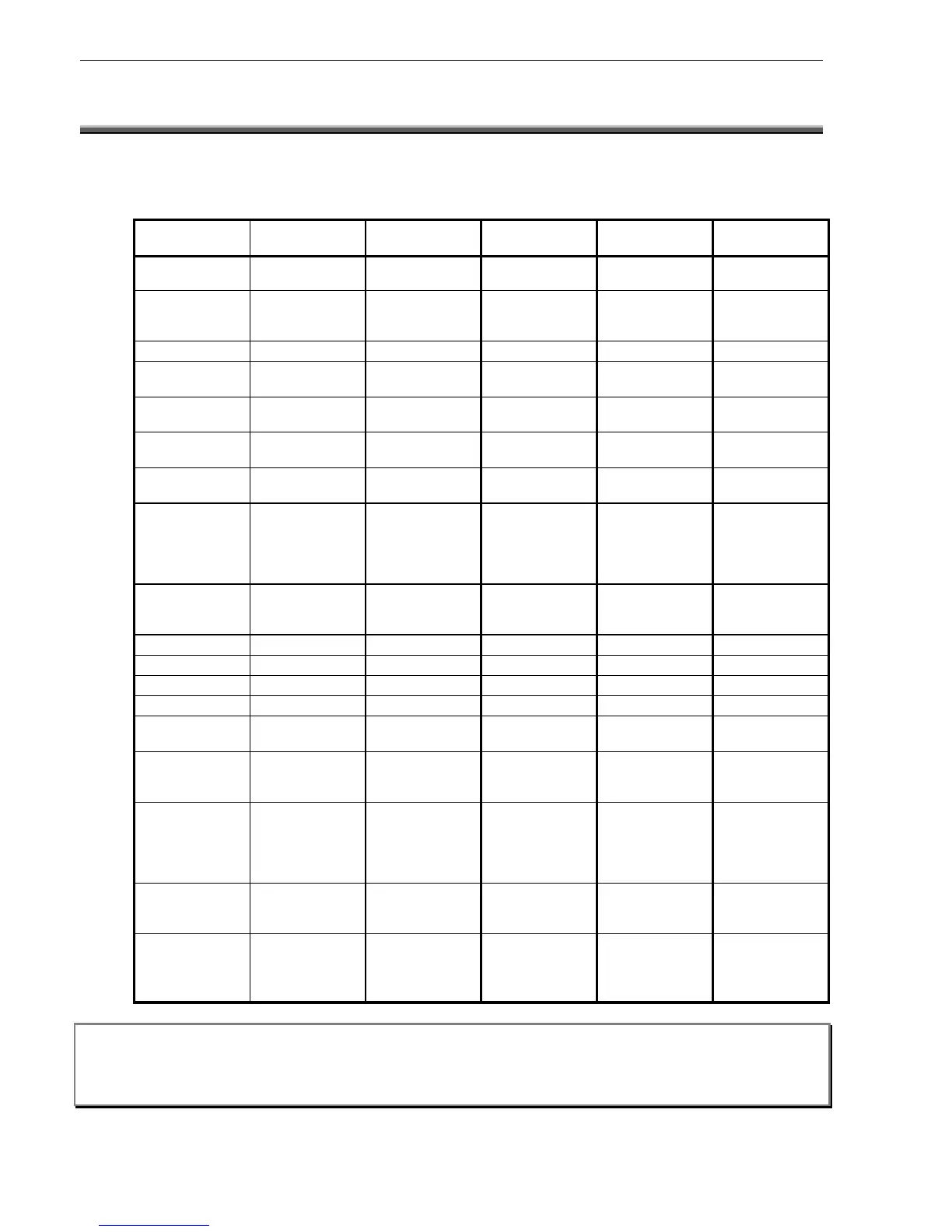
3.3 ELECTRICAL SPECIFICATIONS
Note: All functions and specifications described in this Operators Manual are subject to change without notice.
3
3
.
.
3
3
.
.
1
1
P
P
O
O
W
W
E
E
R
R
S
S
U
U
P
P
P
P
L
L
Y
Y
Parameter PS243
(3Amp)
PS249
(9Amp)
NPS-2
(2.6amp)
NPS-5
(5.5amp)
NPS-11
(11.7amp)
Input Voltage 240V AC +/-
10%
240V AC +/-
10%
110 or 240
(SW select)
Universal Universal
Input Range 216V AC to
254V AC
216 V AC to
254V AC
85-132/170-
264VAC
(SW select)
85-264VAC
Auto Ranging
88-264VAC
Auto Ranging
Output Voltage 24V DC nom. 24V DC nom. 24V DC nom. 24V DC nom. 24V DC nom.
27.6V DC no
load
27.6V DC no
load
27.6V DC no
load
27.6V DC no
load
27.6V DC no
load
26.5 V DC full
load
26.5V DC full
load
27.6V DC full
load
27.6V DC full
load
27.6V DC full
load
Adjustable
Range
12V DC to 30V
DC
12V DC to 30V
DC
+/-10% +/-10% 26V to 32V
Rated Current
Of Power Supply
3.0A @ 26.5V
DC
9.0A @ 26.5V
DC
2.6A @ 27V DC 5.5A @ 27V DC 11.7 @ 27V DC
Overload
Current Device
7.4A @ Short
Circuit
20A @ Short
Circuit
105% to 150%
of rated power –
auto recovery
after fault
removal
105% to 150%
of rated power –
auto recovery
after fault
removal
105% to 135%
of rated power –
auto recovery
after fault
removal
Secondary
Transformer
Fuse
5A 15A N/A N/A N/A
Max Ripple 150mV p-p 150mV p-p 120mV p-p 150mV p-p 200mV p-p
Load Regulation 2% 2% ± 0.5% ± 0.5% ± 0.5%
Line Regulation 2% 2% ± 0.5% ± 0.5% ± 0.2%
Efficiency >80% >80% 82% 84% 88%
Battery Test Internal: 15
ohms
Internal: 15
ohms
External Load External Load External Load
Battery Test
Relay Contact
Rating
10A 15A N/A N/A N/A
Indicators Mains On,
Output On
Mains On,
Output On
Mains On,
Charger Fault,
Battery Fault,
Battery test,
Batt test inhibit
Mains On,
Charger Fault,
Battery Fault,
Battery test,
Batt test inhibit
Mains On,
Charger Fault,
Battery Fault,
Battery test,
Batt test inhibit
Status Indicators By External
Interface or FIP
By External
Interface or FIP
Onboard LED or
External
Interface or FIP
Onboard LED or
External
Interface or FIP
Onboard LED or
External
Interface or FIP
Environmental
-10C to +55C
Dry heat
+ 40C @ 93%
RH
-10C to +55C
Dry heat
+ 40C @ 93%
RH
-10C to +55C
Dry heat
+ 40C @ 93%
RH
-10C to +55C
Dry heat
+ 40C @ 93%
RH
-10C to +55C
Dry heat
+ 40C @ 93%
RH
WARNING: Severe damage may occur if the batteries are connected incorrectly.
Note: When annunciators or field modules are powered from external power supplies, use a separate conductor to
connect the main power supply common terminal (-0V) to the remote power supplies common terminal (-0V).

 Loading...


