Appendix
126 AFP-2800/2802 Manual – P/N 11249 11-Mar-08
8
8
.
.
9
9
.
.
4
4
C
C
O
O
M
M
M
M
O
O
N
N
A
A
L
L
A
A
R
R
M
M
,
,
B
B
E
E
L
L
L
L
A
A
N
N
D
D
W
W
A
A
R
R
N
N
I
I
N
N
G
G
S
S
Y
Y
S
S
T
T
E
E
M
M
O
O
U
U
T
T
P
P
U
U
T
T
S
S
Bell and Warning System outputs will activate 3 seconds after a common alarm to comply with NZS4512: 204.13.
The intent of this clause is to ensure that an alarm is sent to the fire brigade before switching on any heavy loads,
just in case the battery is faulty and fails when the heavy loads are switched on. All outputs that switch heavy
loads using the FIP power supply should also have an activation delay greater than 2 seconds. This delay can be
achieved using a timer in the output script. E.g. CA AND T3;
PR1 – Bell Output (Common alarm (CA) with 3 second delay)
PR2 – Warning System Output ((Common alarm (CA) with 3 second delay)
Note: Any script entered by the user for this output will over-ride the above functionality which is equivalent to the
following script: (CA OR WI) AND !BI AND T3;
PR3 – General Purpose
PR4 – General Purpose
PR5 – Alarm LED Output (Common alarm)
PR6 – Defect LED Output (Common Fault – normally energised)
PR7 – System Normal LED Output (!CA AND !CF – normally energised)
PR8 – General Purpose
Two other relays such as XR1 & XR2 should be reserved to generate an alarm and fault signal for use with
approved Signal Generating Devices (SGD).
8
8
.
.
9
9
.
.
5
5
S
S
Y
Y
S
S
T
T
E
E
M
M
S
S
T
T
A
A
T
T
U
U
S
S
&
&
Z
Z
O
O
N
N
E
E
A
A
L
L
A
A
R
R
M
M
L
L
E
E
D
D
I
I
N
N
D
D
I
I
C
C
A
A
T
T
I
I
O
O
N
N
S
S
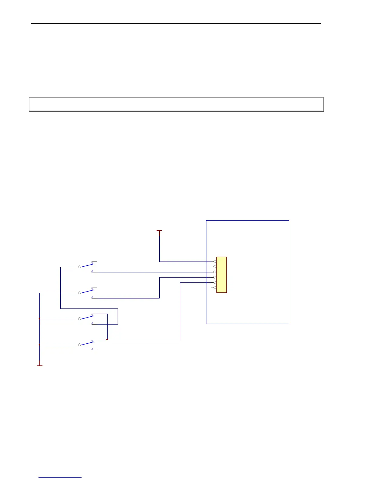
Panel Relays on FIM must be hardwired to an IFS-722 common status LED PCB providing Alarm, Defect and
Normal indications for the system. Every NZ panel should have a LDM-32a lamp driver, ACM-32a or IFS-721 LED
Expansion board installed to allow annunciation of zone alarms on the backboard.
.
24V
1
2
3
4
5
6
J1
NORMAL
ALARM
DEFECT
PR5-CA
PR6-!CF
RELAYONIFS-720
CPUMONITORBOARD
PR7-!CFAND!CA
NE
NE
NE
IFS722A
COMMONLEDBOARD
0V
24V
Relays on FIM are shown in the de-energised position.
Relays marked NE are normally energised in the normal panel operating state.
PR5 energises on alarm
PR6 de-energises on fault
PR7 de-energises on alarm or fault
Relay on IFS-720 de-energises on a processor fault.
8
8
.
.
9
9
.
.
6
6
S
S
H
H
O
O
R
R
T
T
C
C
I
I
R
R
C
C
U
U
I
I
T
T
S
S
O
O
N
N
C
C
O
O
N
N
V
V
E
E
N
N
T
T
I
I
O
O
N
N
A
A
L
L
A
A
Z
Z
F
F
S
S
Short circuits on all AZFs will be treated as faults and not alarms. If a contact is used to activate an AZF for
purposes other than conventional detection then a 680 ohm resistor should be used instead of a short to simulate
a conventional circuit in alarm.

 Loading...


