Appendix
AFP-2800/2802 Manual – P/N 11249 11-Mar-08 137
8
8
.
.
1
1
3
3
.
.
7
7
L
L
C
C
D
D
8
8
0
0
D
D
I
I
S
S
P
P
L
L
A
A
Y
Y
I
I
N
N
T
T
E
E
R
R
F
F
A
A
C
C
E
E
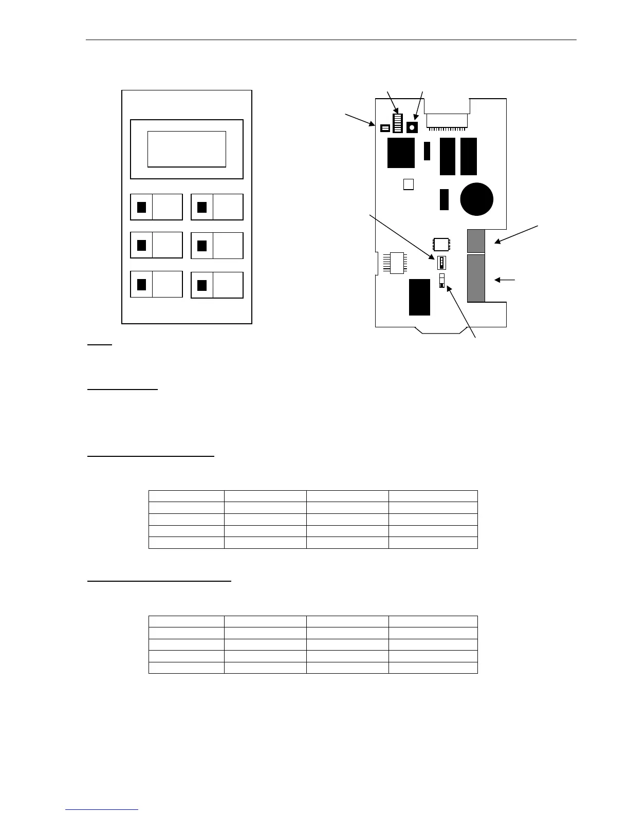
Note:
Both Operating Mode switches (SW4 & SW5) on the PCB must be set for ACS Mode (the UP position).
Event sounder:
Setting DIP Switch 1 of SW1 to OFF will disable the buzzer for alarms. Setting DIP Switch 2 of SW1 to OFF will
disable the buzzer for faults. Setting DIP Switch 3 of SW1 to OFF will disable the buzzer for Isolates. If the buzzer
is enabled, pressing the “MUTE” button will silence the buzzer until a new event is received.
Addressing Terminal Mode:
SW2 & SW3 set the address as per the table below. Note that “200” is added to the actual values of SW2 & SW3
to give an address in the range 201 – 239. Setting all switches to off will take the LCD-80 offline.
SW3-1 SW3-2 SW2 Actual Address
OFF OFF 1 – 9 201 – 209
ON OFF 0 – 9 210 – 219
OFF ON 0 – 9 220 – 229
ON ON 0 – 9 220 – 239
Addressing Annunciator Mode:
SW2 & SW3 set the address as per the table below. Note that “100” is added to the actual values of SW2 & SW3
to give an address in the range 101 – 139. Setting all switches to off will take the LCD-80 offline.
SW3-1 SW3-2 SW2 Actual Address
OFF OFF 1 – 9 101 – 109
ON OFF 0 – 9 110 – 119
OFF ON 0 – 9 120 – 129
ON ON 0 – 9 120 – 139

 Loading...


