Appendix
100 AFP-2800/2802 Manual – P/N 11249 11-Mar-08
8.5 RECOMMENDED CABLING REQUIREMENTS
8
8
.
.
5
5
.
.
1
1
R
R
S
S
-
-
4
4
8
8
5
5
R
R
I
I
N
N
G
G
C
C
O
O
M
M
M
M
U
U
N
N
I
I
C
C
A
A
T
T
I
I
O
O
N
N
C
C
A
A
B
B
L
L
I
I
N
N
G
G
Applies to:
Ring 1 communication lines
Annunciator communication lines
Requirements:
Style
Minimum 0.75mm
2
x 2 core Twisted Pair Shielded communications cable
(+ separate 2 core cable for 24VDC module power )
Max distance Communications cable: 1000M between modules with 1.5mm
2
cable
(24VDC power cable distance will be determined by voltage drop)
Notes:
Maximum of 16 annunciators between any two modules
Fire rated cables may be required as per AS1670, AS1668, AS2118
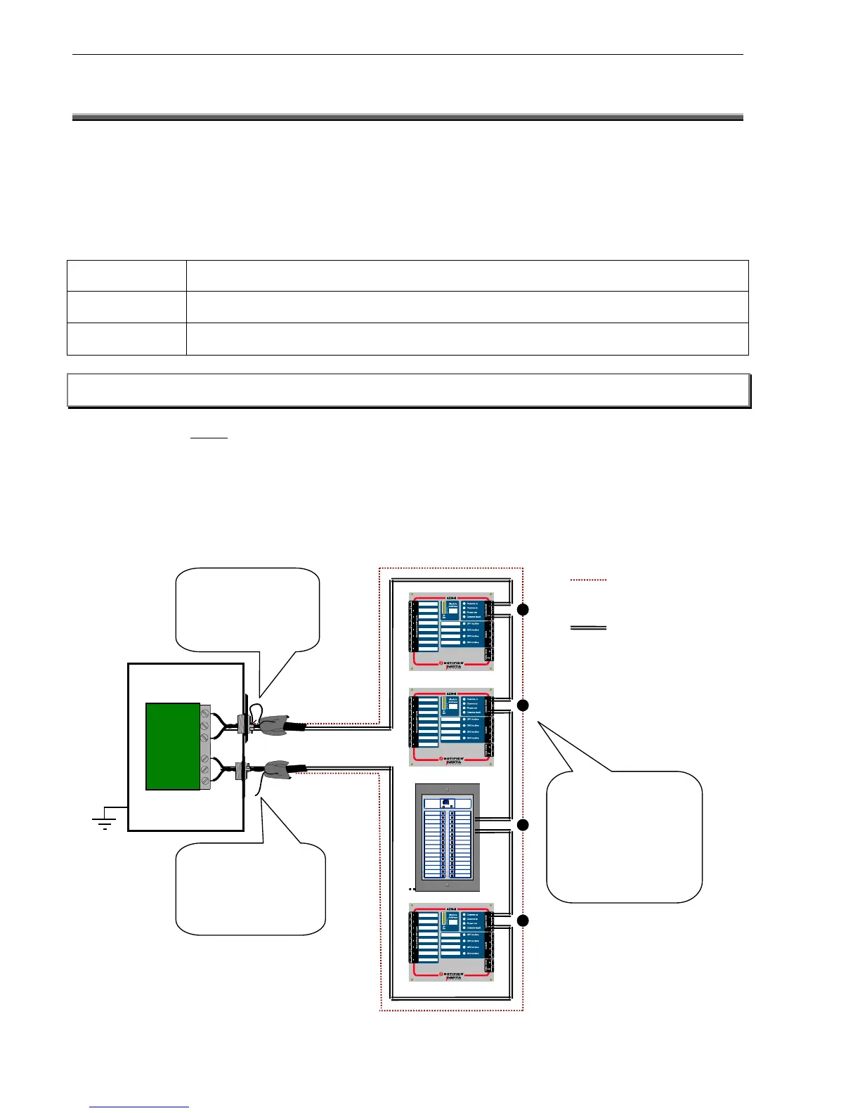
Note: When annunciators or Field Modules are powered from external power supplies, use a separate conductor to
connect the main power supply common terminal (-0V) to the remote power supplies common terminal (-0V).
The EIA-485 circuit MUST be wired using a twisted-pair shielded cable. Do not run cable adjacent to, or in the
same conduit as, 240-volt AC service, noisy electrical circuits that are powering mechanical bells or horns, audio
circuits above 25 VRMS or motor control circuits. All enclosures, including the FIP cabinet, must be connected to
electrical earth! Never use the shield as an earthing conductor.
Terminate the shield at the outside of the FIP cabinet (ground). Where this is not possible, the shield must be
terminated to physical ground immediately adjacent to cable entry. Between Field modules, connect shields
together outside of their respective enclosures. Make sure that the shield is only grounded at the FIP and not at
the modules or annunciators. Do not ground both ends of the shield; one end should be left floating.
FIP Cabinet

 Loading...


