Appendix
AFP-2800/2802 Manual – P/N 11249 11-Mar-08 131
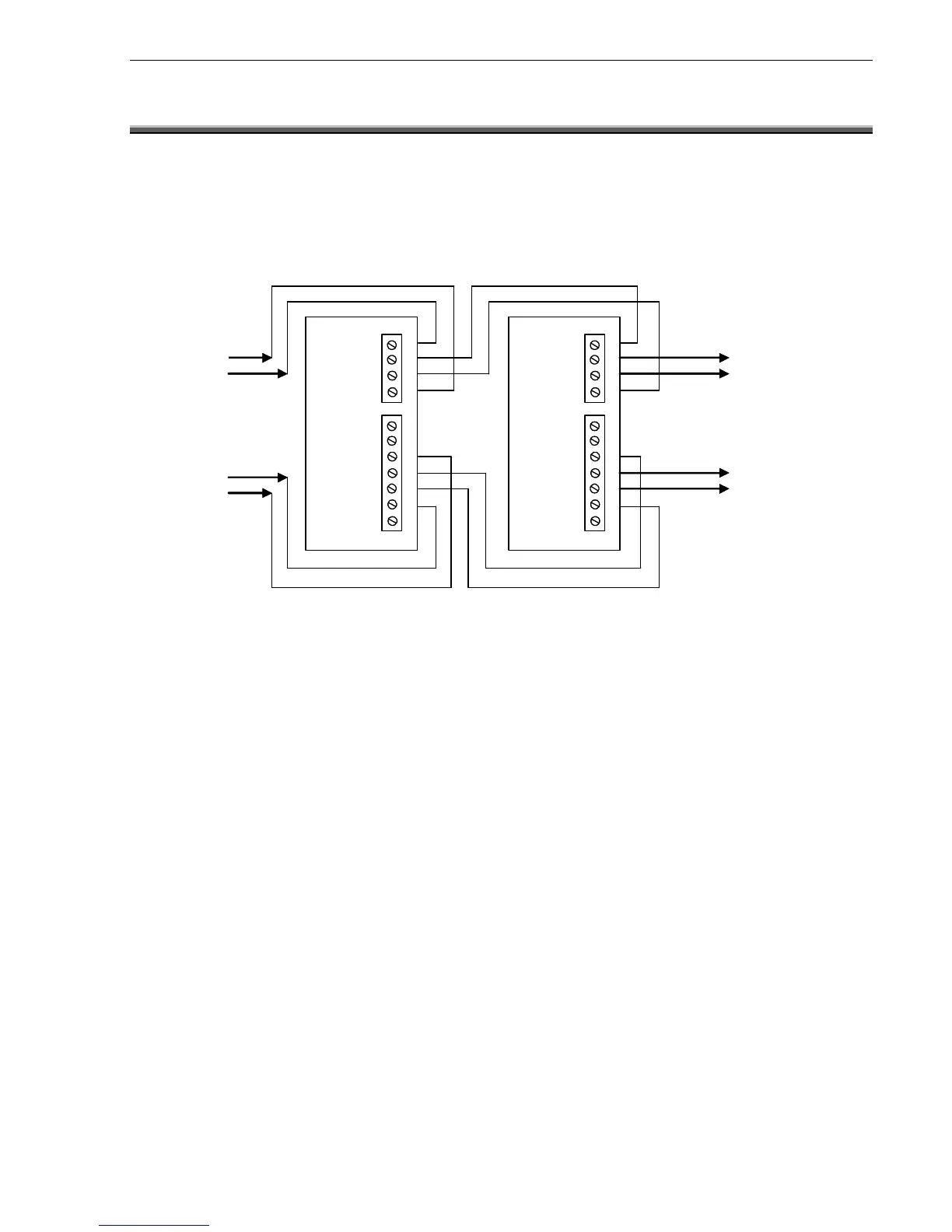
8.13 ANNUNCIATOR CONNECTION
8
8
.
.
1
1
3
3
.
.
1
1
R
R
S
S
4
4
8
8
5
5
C
C
O
O
M
M
M
M
S
S
A
A
N
N
D
D
P
P
O
O
W
W
E
E
R
R
C
C
O
O
N
N
N
N
E
E
C
C
T
T
I
I
O
O
N
N
S
S
The connection diagram below applies to all annunciators (ACM-16AT, ACM-32A, SCS-8, LDM-32) and the
LCD80 Display Interface Unit.
RS 485 IN -
RS 485 OUT -
RS 485 OUT +
RS 485 IN +
24VDC
24VDC
0VDC
Notes:
1) Field annunciators (and LCD80 Display Interface Units) must be multi-drop connected on Ring 1 as shown in
the above diagram; a T-connection (or spur) is not allowed. No termination resistor is to be used and the
shield shall be connected to earth.
2) Local annunciators (and LCD80 Display Interface Units) may be connected to the local annunciator chain
connector on the lower left edge of the Termination Board. This connector is only to be used for annunciators
(and LCD80 Display Interface Units) that are mounted internally to the fire panel or in a cabinet immediately
adjacent to it. No termination resistor is to be used for this mode of connection since there is a built in 150
ohm resistor on the termination board.
3) There can be a maximum of 16 annunciators (and LCD80 Display Interface Units) between any 2 consecutive
field modules (or port A and port B if no field modules are present on the Ring).
4) Between Field modules, connect shields together outside of their respective enclosures. Make sure that the
shield is only grounded at the FIP and not at the modules or annunciators. Do not ground both ends of the
shield; one end should be left floating.
5) When annunciators or Field Modules are powered from external power supplies, use a separate conductor to
connect the main power supply common terminal (-0V) to the remote power supplies common terminal (-0V).

 Loading...


