MIPI CSI Video Input
NVIDIA Jetson TX2 NX DG-10141-001_v1.1 | 48
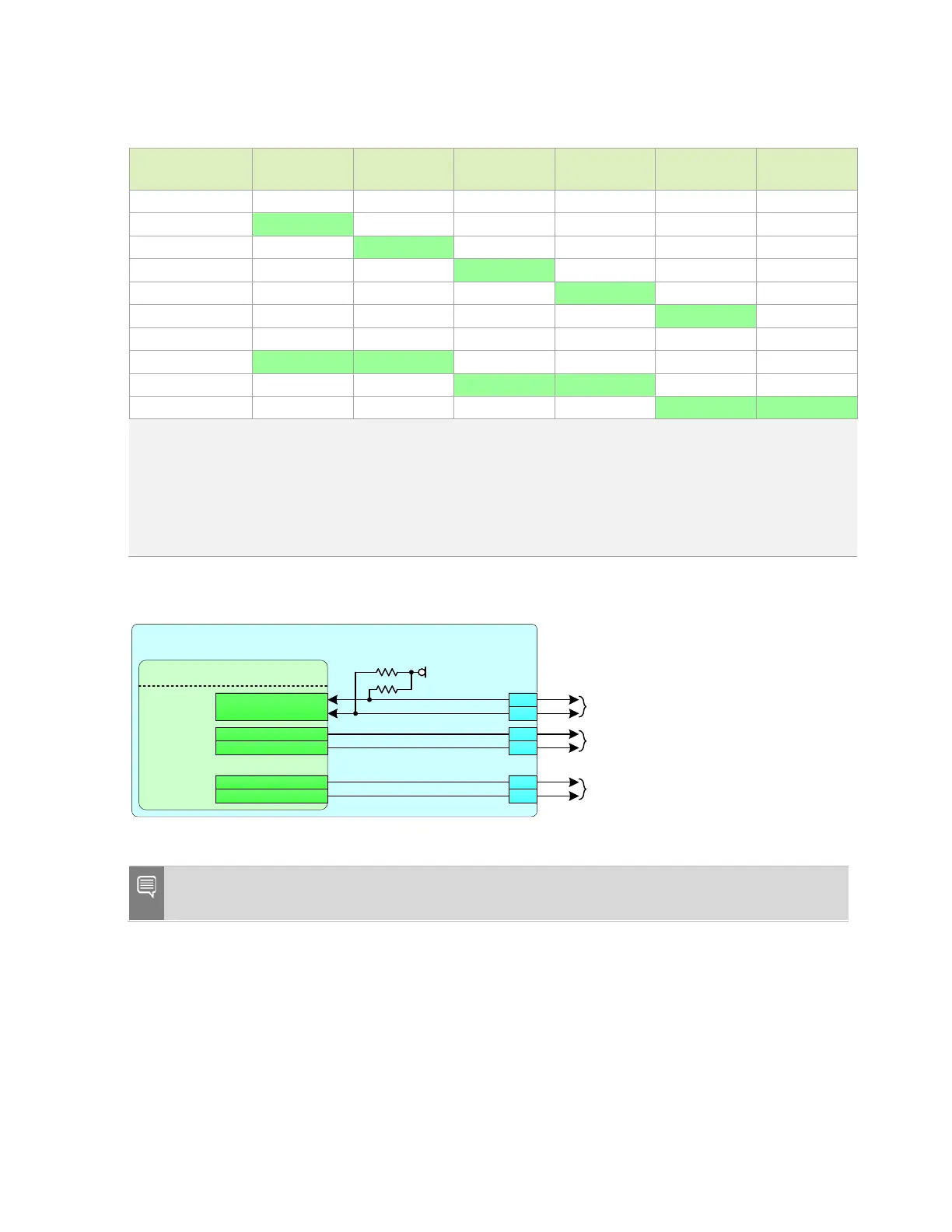
Table 8-3. CSI Configuration
Cameras CSI_0
CLK/Data[1:0]
CSI_1
CLK/Data[1:0]
CSI_2
CLK/Data[1:0]
CSI_3
CLK/Data[1:0]
CSI_4
CLK/Data[1:0]
CSI_4
Data[3:2]
1 of 5 cameras √
2 of 5 cameras √
3 of 5 cameras √
4 of 5 cameras √
5 of 5 cameras √
1 of 3 cameras √ √
2 of 3 cameras √ √
3 of 3 cameras √ √
Notes:
1. For 4-lane configurations, CSI_[3,1]_CLK are not used.
2. CSI 4 can be used as as a x1, x2, or x4 CSI interface.
3. Combinations of 2-lane and 4-lane cameras are supported as long as the 4-lane camera uses one of the indicated
combinations.
4.
Each 2-lane options shown above can also be used for one single lane camera.
Figure 8-2. Available Camera Control Pins
Jetson
Tegra
CAM
CAM_I2C_SCL
CAM_I2C_SDA
EXTPERIPH1_CLK
EXTPERIPH2_CLK
GPIO _CA M1
GPIO _CA M4
2. 2kΩ
2. 2kΩ
VDD_3V3_SY S
Camera
I2C
Camera 0
Clock/Control
Camera 1
Clock/Control
CAM_I2C_SCL
CAM_I2C_SDA
CAM0_MCLK
CAM0_PWDN
CAM1_MCLK
CAM1_PWDN
215
116
114
213
120
122
Note: The CAM_I2C interface is connected to the power monitor device on the module which
uses I2C address 7’h40.

 Loading...


